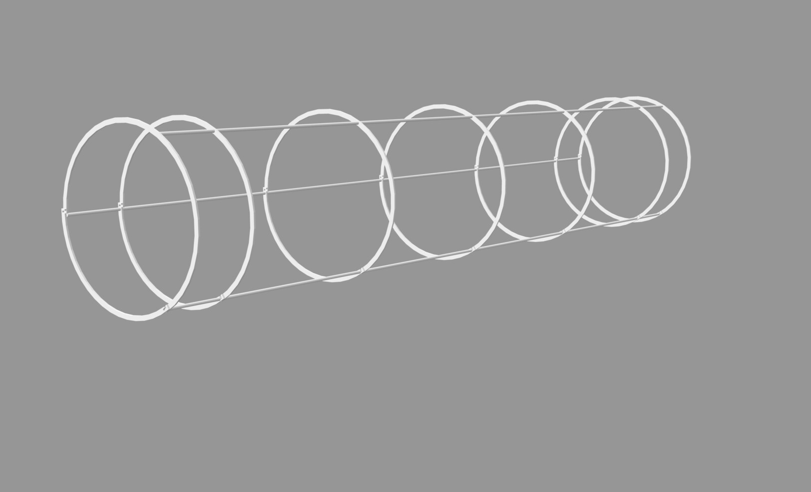
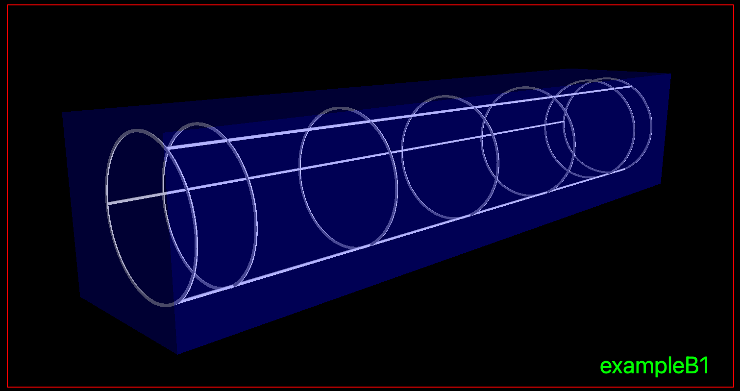
I am trying to make a volume using mulitple individual parts (3 cylindrical rods and 7 circular rings). I know I can put 2 parts together using G4UnionSolid but I am not sure how to place all 7 rings and the 3 rods in the parameters of G4UnionSolid class.
Hello,
Combine part 1 and part 2 to part “A”.
Combine part A and part 3 to part “B”.
Combine part B and part 4 to part “C”.
… and so on …
As far as i know G4UnionSolid can only take two parts to combine.
Regards
Max
That’s what I thought. But I wondered if there is a smart way of doing it
Take a look at G4MultiUnion.hh. It let’s you supply a whole list of solids which all get unioned together in one step. That avoids the significant performance loss from cascaded boolean solids.
	G4Tubs* ring1 = new G4Tubs("ring1", 129*mm, 134*mm, 2/2*mm, 0, 2*pi);
	G4Tubs* ring2 = new G4Tubs("ring2", 129*mm, 134*mm, 2/2*mm, 0, 2*pi);
	G4Tubs* ring3 = new G4Tubs("ring3", 129*mm, 134*mm, 2/2*mm, 0, 2*pi);
	G4Tubs* ring4 = new G4Tubs("ring4", 129*mm, 134*mm, 2/2*mm, 0, 2*pi);
	G4Tubs* ring5 = new G4Tubs("ring5", 129*mm, 134*mm, 2/2*mm, 0, 2*pi);
	G4Tubs* ring6 = new G4Tubs("ring6", 129*mm, 134*mm, 2/2*mm, 0, 2*pi);
	G4Tubs* ring7 = new G4Tubs("ring7", 129*mm, 134*mm, 2/2*mm, 0, 2*pi);

  G4Tubs* rod1 = new G4Tubs("rod1", 0.0*mm, 2.5*mm, 1400/2*mm, 0, 2*pi);
	G4Tubs* rod2 = new G4Tubs("rod2", 0.0*mm, 2.5*mm, 1400/2*mm, 0, 2*pi);
	G4Tubs* rod3 = new G4Tubs("rod3", 0.0*mm, 2.5*mm, 1400/2*mm, 0, 2*pi);

  G4UnionSolid* ring12 = new G4UnionSolid("ring12", ring1, ring2, 0, G4ThreeVector(0, 0, -300*mm));
	G4UnionSolid* ring123 = new G4UnionSolid("ring123", ring12, ring3, 0, G4ThreeVector(0, 0, -600*mm));
	G4UnionSolid* ring1234 = new G4UnionSolid("ring1234", ring123, ring4, 0, G4ThreeVector(0, 0, -700*mm));
	G4UnionSolid* ring12345 = new G4UnionSolid("ring12345", ring1234, ring5, 0, G4ThreeVector(0, 0, 300*mm));
	G4UnionSolid* ring123456 = new G4UnionSolid("ring123456", ring12345, ring6, 0, G4ThreeVector(0, 0, 600*mm));
	G4UnionSolid* ring1234567 = new G4UnionSolid("ring1234567", ring123456, ring7, 0, G4ThreeVector(0, 0, 700*mm));

	G4UnionSolid* ring1234567rod1 = new G4UnionSolid("ring1234567rod1", ring1234567, rod1, 0, G4ThreeVector(134.0*mm, 0.0*mm, 0*mm));
	G4UnionSolid* ring1234567rod2 = new G4UnionSolid("ring1234567rod1", ring1234567rod1, rod2, 0, G4ThreeVector(-67.0*mm, 116.047*mm, 0*mm));
	G4UnionSolid* ring1234567rod3 = new G4UnionSolid("ring1234567rod1", ring1234567rod2, rod3, 0, G4ThreeVector(-67.0*mm, -116.047*mm, 0*mm));
This is what I ended up doing. It works but very inefficiently. I tried implementing G4MultiUnion but that gave me errors and I couldn’t fix it then
Nested unions like that are terribly inefficient; that’s why G4MultiUnion was developed. It looks to me like you aren’t apply any rotations to your objects, just positional placements. That should make it much easier to deal with.
With G4MultiUnion the very first solid on the list defines the coordinate system (x,y,z orientation and the location of (0,0,0)). All of these other solids should have their placements done relative to that first one, and when you place the whole solid, the placement specifies where that origin (0,0,0) goes.
It looks like that’s exactly what you’re doing. If I understand right, your “ring1” is the one in the center along the axis. Then ring2, ring3, ring4 are sequentially farther away along -z, and ring5, ring6, ring7 are sequentially along +z.
So with G4MultiUnion, you would do something like:
    G4MultiUnion* railgun = new G4MultiUnion("railgun");
    railgun->AddNode(ring1, G4Transform3D::Identity);
    railgun->AddNode(ring2, G4TranslateZ3D(-300*mm);
    railgun->AddNode(ring3, G4TranslateZ3D(-600*mm);
    railgun->AddNode(ring4, G4TranslateZ3D(-700*mm);
    railgun->AddNode(ring5, G4TranslateZ3D(300*mm);
    railgun->AddNode(ring6, G4TranslateZ3D(600*mm);
    railgun->AddNode(ring7, G4TranslateZ3D(700*mm);
    railgun->AddNode(rod1, G4Translate3D(134.0*mm, 0.0*mm, 0*mm);
    railgun->AddNode(rod2, G4Translate3D(-67.0*mm, 116.047*mm, 0*mm);
    railgun->AddNode(rod3, G4Translate3D(-67.0*mm, -116.047*mm, 0*mm);
Remark 1. In your case all rings and rods are the same. It is not necessary to construct a separate volume for each ring and each rod.
Remark 2. Geant4 is not a CAD system, it’s not a good practice to apply a CAD approach to construction of geometry in Geant4. Boolean operations in Geant4 are rather CPU demanding, so it’s better to avoid them. For example in your case the geometry can be defined as a set of separate rings and rods without any impact on the simulation results:
  // Construct ring
  G4double ringRMin = 129*mm, ringRMax = 134*mm, ringThickness = 2.*mm;
  G4Tubs* ringSolid = new G4Tubs("Ring", ringRMin, ringRMax, ringThickness/2., 0., twopi);
  G4LogicalVolume* ringLogical = new G4LogicalVolume(ringSolid, ringMaterial, "Ring");

  // Place rings
  G4double ringZPositions[7] = { -700*mm, -600*mm, -300*mm, 0*mm, 300*mm, 600*mm, 700*mm };
  for (G4int i = 0; i < 7; ++i) {
    new G4PVPlacement(nullptr, G4ThreeVector(0., 0., ringZPositions[i]),
                      ringLogical, "Ring", logicEnv,
                      false, 0, checkOverlaps);
  }

  // Constrcut short and long rods
  G4double rodR = 2.5*mm;
  G4double shortRodLength = ringZPositions[1] - ringZPositions[0] - ringThickness;
  G4double longRodLength  = ringZPositions[2] - ringZPositions[1] - ringThickness;
  G4Tubs* shortRodSolid = new G4Tubs("Rod", 0*mm, rodR, shortRodLength/2., 0, twopi);
  G4Tubs* longRodSolid = new G4Tubs("Rod", 0*mm, rodR, longRodLength/2., 0, twopi);
  G4LogicalVolume* shortRodLogical = new G4LogicalVolume(shortRodSolid, rodMaterial, "Rod");
  G4LogicalVolume* longRodLogical = new G4LogicalVolume(longRodSolid, rodMaterial, "Rod");

  // Set rod positions
  G4double rodZPositions[6];
  for (G4int i = 0; i < 6; ++i) {
    rodZPositions[i] = (ringZPositions[i] + ringZPositions[i+1])/2.;
  }
  G4TwoVector rodXYPositions[3];
  for (G4int i = 0; i < 3; ++i) {
    G4double r = (ringRMin + ringRMax)/2.;
    G4double phi = i*120*deg;
    rodXYPositions[i].set(r*std::cos(phi), r*std::sin(phi));
  }

  // Place rods
  for (G4int i = 0; i < 3; ++i) {
    G4ThreeVector position;
    // Set x and y
    position.setX(rodXYPositions[i].x());
    position.setY(rodXYPositions[i].y());

    // Set z and place
    position.setZ(rodZPositions[0]);
    new G4PVPlacement(nullptr, position,
                      shortRodLogical, "Rod", logicEnv,
                      false, 0, checkOverlaps);
    for (G4int k = 1; k < 5; ++k) {
      position.setZ(rodZPositions[k]);
      new G4PVPlacement(nullptr, position,
                        longRodLogical, "Rod", logicEnv,
                        false, 0, checkOverlaps);
    }
    position.setZ(rodZPositions[5]);
    new G4PVPlacement(nullptr, position,
                      shortRodLogical, "Rod", logicEnv,
                      false, 0, checkOverlaps);

  }
Thanks a lot! This is much easier than what I implemented
Thanks, I will look into G4MultiUnion and try give it a try
I ended up using this code and now the simulation time has improved significantly. Thank you so much!
Hi all! Regarding this topic, I have a doubt about the relative positions of the different volumes.
If I understand correctly the position passed to AddNode must be the one relative to the position of the first element of the union. However, in the example of the G4 manual, the first volume has a position itself (I attach a screenshot of the manual).
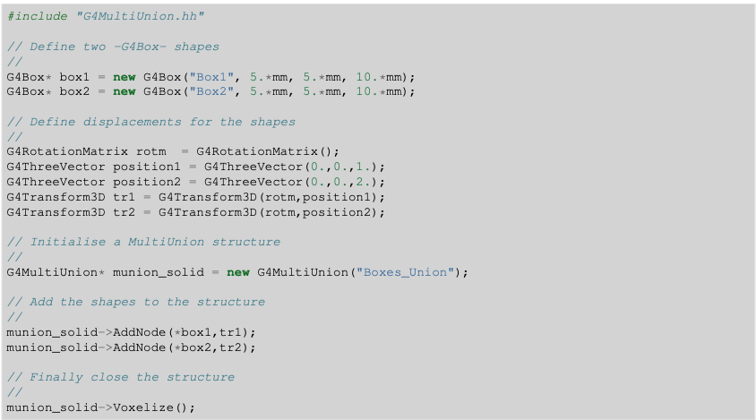
In this case, aren’t the placements of the other volumes done relatively to the first element anymore? Or how does the position of the first element affect the whole structure?
Thanks for your help.
In fact, it seems to me that the volumes are placed with respect to (0, 0, 0), not relatively to the first volume. If the first volume is not translated/rotated, therefore it’s the same, but it is not necessarily the case.
In my particular case it is easier for me to place all the elements of the union relatively to a common origin, instead of relatively to the first one and I think it’s great that G4 allows for this possibility.
Can you confirm that my understanding is correct?
Correct. There is no difference in the placement of the first constituent solid and the others, all of them are placed in the local coordinate system of the G4MultiUnion solid.
I guess my question is what defines “the local coordinate system of the G4MultiUnion solid”?
With a regular boolean G4UnionSolid, the local coordinate system is defined by the first argument, and the second argument is placed in that frame.
If you pass in a non-identity G4Transform3D for the first G4MultiUnion::AddNode() call, does that just implicitly define a local coordinate system from which the transform makes sense?
Each solid has its own local coordinate system (frame).
In case of a regular Boolean solid, the first constituent solid is placed without transformation, its frame coincides with the frame of the Boolean solid, and we can say that the position of the second constituent solid is specified relative to the first constituent solid.
In case of G4MultiUnion all constituent solids are given with a transformation, which specified their position in the frame of the G4MultiUnion solid. You can change the order of AddNode() calls, the resulting solid will remain unchanged.
My understanding is that all solids are placed relatively to a common origin point, which will be also the center of the resulting multiunion volume. This center will be used for the placement of the multiunion volume. At least, this understanding seems to explain what I see in my simulation.