Hello,
I am using Geant4.10.6.p01 on Windows 10.
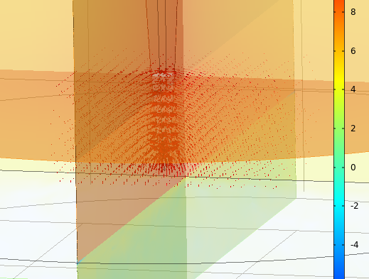
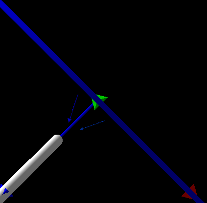
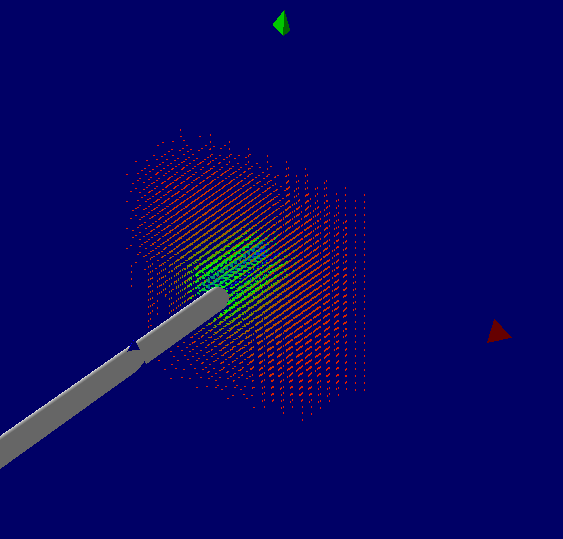
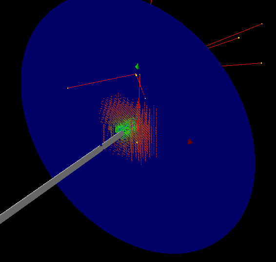
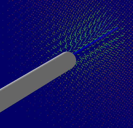
I am attempting to setup a non-uniform electric field around a sharp tip. The simulation volume is on the order of a few 100 nanometers.
Thus far, I have copied the relevant files from the field02 example and managed to create a uniform electric field in my model. I can fly the electrons and I see the trajectories bend in the field and I can view the field with the /vis/scene/add/electricField command.
Now I try to change the field to a non-uniform electric field. There is no example provided for a non-uniform electric field, but there is one for a non-uniform magnetic field (purging magnet). Hence I have taken this code, but instead of creating a magnetic field, I create an electric field (for the moment using the same file that purging magnet uses). The file appears to be read correctly as I get this output which is very similar to the output of the purging magnet example.
Electric field
—> Reading the field grid from PurgMag3D.TABLE …
[ Number of values x,y,z: 6 6 10 ]
—> … done reading
—> assumed the order: x, y, z, Bx, By, Bz
—> Min values x,y,z: -5e-06 -5e-06 -2.6e-05 cm
—> Max values x,y,z: 5e-06 1.7e-05 1e-05 cm
—> The field will be offset by 0 cm
After reordering if neccesary
—> Min values x,y,z: -5e-06 -5e-06 -2.6e-05 cm
—> Max values x,y,z: 5e-06 1.7e-05 1e-05 cm
—> Dif values x,y,z (range): 1e-05 2.2e-05 3.6e-05 cm in z
F02ElectricFieldSetup: The minimal step is equal to 0.001 mm
G4ClassicalRK4 is called
However, I do not see the electron trajectories curve and when I try to view the electric field I get the message:
No Electric field in this extent.
The electric field constructor (taken from Field02 example) is this (I commented out the line where a uniform field is setup):
F02ElectricFieldSetup::F02ElectricFieldSetup()
: fMinStep(0.0010mm), // minimal step of 1 micrometers
fFieldManager(0),
fChordFinder(0),
fEquation(0),
fEMfield(0),
fElFieldValue(),
fStepper(0),
fIntgrDriver(0),
fStepperType(4), // ClassicalRK4 – the default stepper
fFieldMessenger(nullptr)
{
// fEMfield = new G4UniformElectricField(G4ThreeVector(0.0,-1.0kilovolt/cm,0.0));
G4double zOffset = 0.0 * mm;
fEMfield = new PurgMagTabulatedEField3D(“PurgMag3D.TABLE”, zOffset);
fEquation = new G4EqMagElectricField(fEMfield);
fFieldManager = GetGlobalFieldManager();
UpdateIntegrator();
fFieldMessenger = new F02FieldMessenger(this);
}
The code for PurgMagTabulatedEField3D is essentially the same as PurgMagTabulatedField3D in the purging magnet example.
The major difference is that PurgMagTabulatedEField3D has the following code in the include file.
class PurgMagTabulatedEField3D
#ifndef STANDALONE
: public G4ElectricField
#endif
so PurgMagTabulatedEField3D inherits from G4ElectricField whereas PurgMagTabulatedField3D (from the purging magnet example) inherits from G4MagneticField.
Any advice/suggestions would be welcome.
Thanks
Chris