I managed to edit the PurgMagTabulatedField.cc and .hh appropriately and change them from magnet field to electric field and import them into field02 and successfully compile and link them.
I’ve called F02TabulatedField (formerly PurgMagTabulatedField) from F02ElectricField by substituting it for the G4UniformElectricField constructor. Using the field map from the Purge_Magnet example (PurgMag3D.TABLE. I know that the physics will be wrong) I was hoping to see some of the field when I set /vis/scene/add/electricField. However nothing is apparent. I also see the dreaded " No Electric field in this extent" warning.
Assuming that my modified code is working how do you go about finding the imported field (whether E-field or Magnetic field)? The majority of the extent of the field in PurgMag3D is within the “world” as defined in my modified field02 example. Need all the field be in the world for it to be displayed?
Hi Tim,
I too got that message, but once I logged in I could see the thread. Anyway, I will copy and paste the thread below. If you want to see the files, let me know and I will try to locate them again.
Chris
Dear Chris Walker,
I read your post “Creating non-uniform electric field” becouse I have your same problems. In details, I create with Comsol an electric field map in my geometry and I use purging magnet example to implement the field, also I modify the purging magnet code to introduce the electric field using hadrontheray example. When I use /vis/scene/add/electricField command I get the message: No Electric field in this extent.
Could you please explain me how you modify your code to solve this problem?
thank you in advance.
Kind regards
Luigi Rinaldi
Hi Luigi,
Sorry, but I got mixed up in how to reply to your message.
I have seen your message, but I am struggling to remember what I did. I note the error message originates here:
modeling/src/G4VFieldModel.cc: G4cout << “No " << fTypeOfField << " field in this extent.” << G4endl;
Basically what happens is that each defined point is checked to make sure that it is inside the current extent. If no points are located within the extent, that message appears. I forget the command, but you can zoom out, and maybe that is all you need to do to increase the size of the extent.
I created a simple model starting with the B1 example and then added an electric field to that. I could dig out that example and send it to you if that helps ?
Best Wishes
Chris
Hi Chris,
thank you for your answer and your advice, now I’ll check the extent’size. Also I created my model starting from example B1. I would be very grateful if you could send me your example.
Best regards
Luigi
Hi Luigi,
I discovered that I put a whole load of other code in my program before I added the electric field. I would guess that you wouldn´t want that, so I just send you the stuff to do with the electric field. It´s possible that I left something out, so get back to me if you have more questions. I note that in order to view the field I used the command
/vis/scene/add/electricField
also there are some commands added via the Messenger class (taken from the F02 example), but when I tried the getField command, my program crashed ! So don´t expect perfection - it´s just for you to get some ideas. The data files for the electric field were generated in COMSOL. I needed several files to generate electric fields at different scales from nm to mm or cm.
By the way, I got to a point where I had some errors telling me that a routine had been called which should only be called when the electron is at a boundary. However, a warning was given as the electron was not at a boundary when the routine was called. I wasn´t sure what caused the problem, but I never got past that issue. If it occurs for you - let me know.
Best Wishes
Chris
Hi Chris,
I really want to thank you for your help, I fixed my code and now I see the electric field. I use COMSOL to simulate my electric field, the lenght unit is meter and the field unit is V/meter. I have a question, after simulating the electric field you save the simulation’s result in a txt file and do you modify your data set before use it in Geant? becouse using debug in Geant I discovered my program reads correctly the positions but the Ex, Ey and Ez components are smaller than a 10^(-9) factor despite I use the same units in Geant, meter for lenght and V/meter for field.
Thank you in advance,
Best regards
Luigi
Hi Luigi,
Sorry for the delayed response. I have been busy with other things as well as not noticing your recent reply. My COMSOL model has data coordinates for the grid in the arrow volume as:
-.001 -.0009 -.0008 -.0007 -.0006 -.0005 -.0004 -.0003 -.0002 -.0001 0 .0001 .0002 .0003 .0004 .0005 .0006 .0007 .0008 .0009 .001
that should be in m
but the output file has -1e6 to +1e6, so 10^9 times larger. My Geant4 program has a length unit of nm, so it reads the data correctly, but I am currently not sure why COMSOL outputs in nm. I could send you the COMSOL file that was used to generate my files which define the electric field if that helps.
The maximum electric field should be somewhat less than 4E5 V/m for the file Topografiner1mm_v2b.txt and that is what I find.
So in my case I have the electric field correct, but the dimensions 10^9 times different !
Best Wishes
Chris
Hi Luigi,
I was just running the COMSOL model again just to check the output and all seems OK, so I think I generated the files I sent to you using an earlier version of the COMSOL model. If the output from the COMSOL model does not conform to what you expect, I would have though you would be able to get some support from COMSOL.
Best Wishes
Chris
Hi Chris,
thank you so much for your help and for your advices, they were very helpful. In Comsol I’ve introduced a volume of air surrounding my entire experimental setup and I’ve changed the field unit in Geant, in this way Geant reproduces the correct field’s value.
Thank you again for everything.
I think I see my problem. Luigi’s COMSOL generated files are reasonably comprehensible and his meshes are regular, ditto for the PurgMag3d file. Whereas mine are generated from the COMSOL physics controlled mesh and quite higgledy-piggledy.
My problem seems to stem from my limited understanding of the COMSOL mesh options. I shall try to generate a regular and presumably rectangular mesh in COMSOL.
I’ve managed to export the e-field from COMSOL in a more sensible format and with a bit of tweaking of the header of that file the modified Geant4 field02 example is reading the file.
But I’m getting the dreaded “no electric field at this extent” message. Inserting a print statement in GetFieldValue and printing out the spatial coords and the vector components at that point reveals that the COMSOL spatial coords of, for example, [7.4 6.66 -1.48] are being displayed by Geant4 as [74 66.6 -14.8] . In other words COMSOL’s centimetres are being shown as millimeters, Geant might taking that millimetre value and “assuming” it’s centimetres and it’s quite possible that there is, indeed, no electric field at that extent. BTW, my COMSOL field was generated in a geometry that should be identical to that described in F02DetectorConstruction.
When you read in a text file of numbers, you either have to multiply by a G4 unit in your reading code, or the number will be interpreted in G4’s internal units. Geant4’s internal units are millimeters. See $G4INCLUDE/CLHEP/Units/SystemOfUnits.hh for all of the units multipliers.
I took a look at the original purging_magnet code, and I see that there’s a local variable there
double lenUnit= meter;
It seems that you correctly modified this line to use centimeter to match your COMSOL model. You wrote:
printing out the spatial coords and the vector components at that point reveals that the COMSOL spatial coords of, for example, [7.4 6.66 -1.48] are being displayed by Geant4 as [74 66.6 -14.8]
That sounds correct: 7.4*centimeter would be printed as 74 if you didn’t divided by your own desired unit in the cout statement.
When you defined your COMSOL geometry, did you follow the Geant4 convention that (0,0,0) is at the center of the volume? We have repeatedly run into a problem in our experiment where someone will generate their COMSOL field model putting Z=0 at the bottom face of the detector, and in the G4 simulation, half the detector has no field, and the other half has a field model that extends out beyond the top face. Make sure that both the dimensions and the ranges of coordinates match between COMSOL and Geant4.
Is the volume associated with the field being placed at (0,0,0) in the world? If it’s offset (i.e., the global-to-local transform is not Identity), then you also need to take that into account.
thanks for replying. Yeah, my COMSOL model was set around the Geant4 convention of (0, 0, 0).
I’ve returned the Tabulated3d field to default by removing my multipliers and [7.4 6.66 -1.48] is now being displayed by Geant4 as [74 66.6 -14.8] and lenUnit is now centimetre.
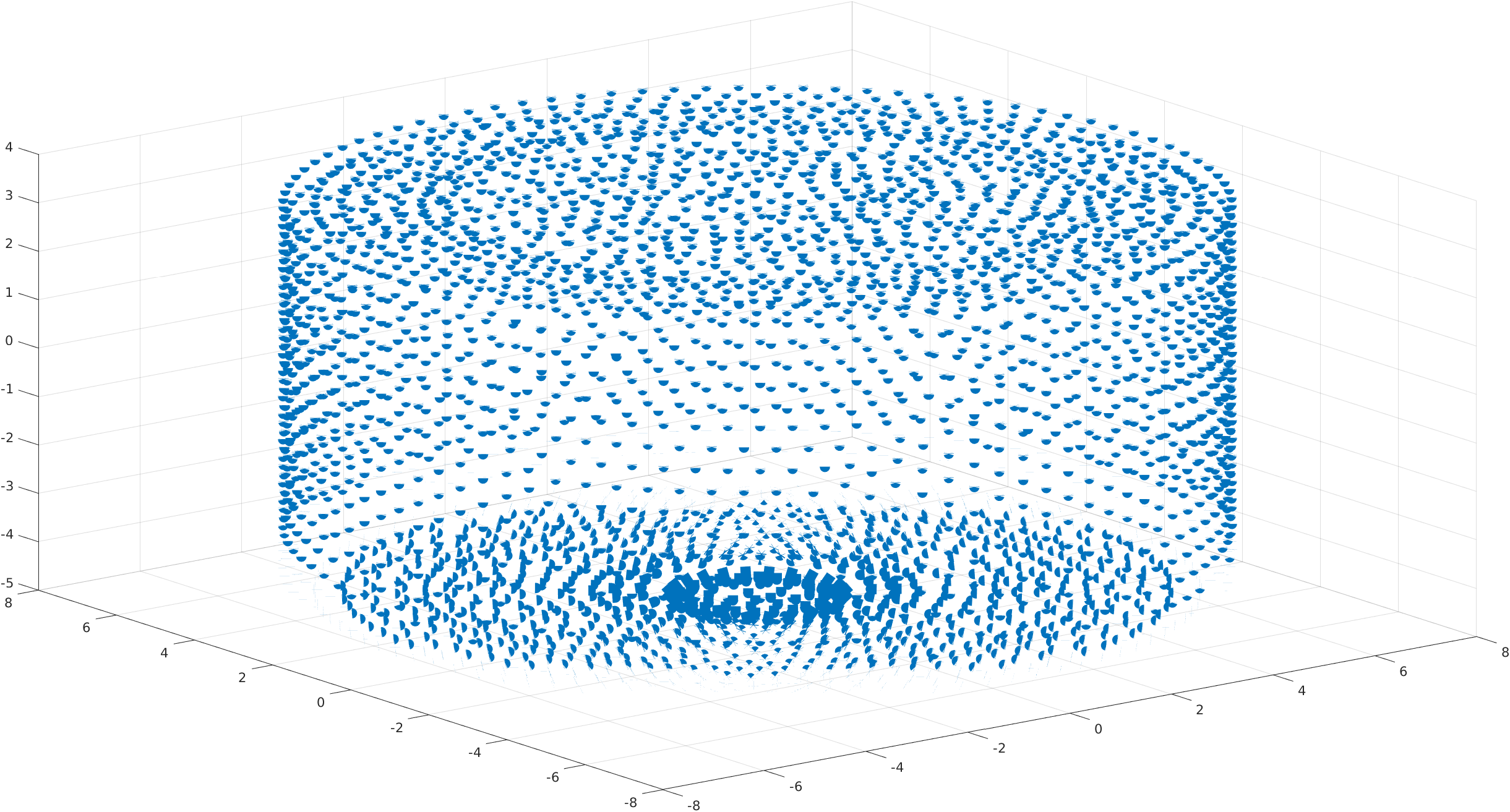
I have previously plotted the COMSOL generated field field in Matlab and it looks sensible (see attachment, apologies for arrow heads).
The messages from TabulatedField3D (below) seem correct. So, the field should be visible.
Some success. I have discovered that not invoking /vis/scene/add/electricField does not interrogate the field (understandably) and, thus does not raise the “no electric field at this extent” message implying, I assume, that the field is just sitting there waiting to be interrogated.
When I run the app the COMSOL generated field is loaded and the limits are set. These limits are as I’d expect from the COMSOL file.
Electric field
—> Reading the field grid from Cauldron_Ex_Ey_Ez_Circumscribed_Rectangle_cm.txt …
[ Number of values x,y,z: 75 75 41 ]
—> … done reading
—> assumed the order: x, y, z, Bx, By, Bz
—> Min values x,y,z: -7.2 -7.4 -4.5 cm
—> Max values x,y,z: 7.4 7.4 3.5 cm
—> The field will be offset by 0 cm
After reordering if neccesary
—> Min values x,y,z: -7.2 -7.4 -4.5 cm
—> Max values x,y,z: 7.4 7.4 3.5 cm
—> Dif values x,y,z (range): 14.6 14.8 8 cm in z
I then /run/beamOn 1 it calls GetFieldValue and after the second step the initially unionised but now ionised particle is within the e-field limits and is captured by the e-field (you can see the e-field at that point):
G4WT0 > *********************************************************************************************************
G4WT1 > Run Summary
G4WT1 > Number of events processed : 0
G4WT1 > User=0.000000s Real=0.000002s Sys=0.000000s [Cpu=0.0%]
G4WT0 > * G4Track Information: Particle = Ra224, Track ID = 1, Parent ID = 0
G4WT0 > *********************************************************************************************************
G4WT0 >
G4WT0 > Step# X Y Z KineE dEStep StepLeng TrakLeng NextVolu Process
G4WT0 > 0 -7.19 mm 1.04 cm 3.5 cm 114 keV 0 eV 0 fm 0 fm World initStep
G4WT0 > 1 -6.98 mm 1.06 cm 3.47 cm 64.5 keV 49.5 keV 999 um 999 um World ionIoni
G4WT0 > #######################################
G4WT0 > ######## Called GetFieldValue ########
G4WT0 > #######################################
G4WT0 > x = -6.9752 [minx = -72][maxx = 74]
G4WT0 > y = 10.6471 [miny = -74][maxy = 74]
G4WT0 > z = 34.7291 [minz = -45][maxz = 35]
G4WT0 > #######################################
G4WT0 > #######################################
G4WT0 > Ex = -3719.58 Ey = 100620 Ez = -364351
Unfortunately the particle gets “stuck” and eventually raises an exception but that’s a topic for another subform. Edit, perhaps it’s not being ionised?
But why, when I do a /vis/scene/add/electricField does it raise a “No Electric field in this extent.” when there is clearly an e-field present?
how’s life in Hebden Bridge? I’ll admit I never got to visit there and it’s unlikely now I’m back in Aus.
I tried your suggestions with the exception of stepping through the code with a debugger but I’m none the wiser. However I did try using the uniform field that is default with the field02 example and some of the daughter product primaries (I expect about 30%) are “picked up” by the e-field and transported. So, in spite of my previous posting and the symptoms indicating that the particles are experiencing an electric field, it may be that they are not be experiencing that e-field hence them getting “stuck”. Perhaps there is a “disconnect” between the volume and the e-field.
To show my ignorance and rustiness of C++ I wonder whether it is possible to check the field from within F02SteppingVerbose?
I’ve managed to get my field02 example running in Xcode. I was expecting far worse but it wasn’t too bad at all. But I’m very rusty with debuggers and haven’t used them for over 20 years.
But it was the above quote by Chris that finally cracked the field visualization issue.
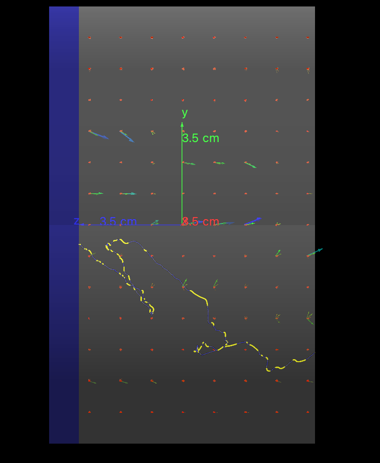
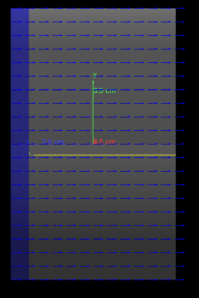
I’m now having tracking issues. With an e-field running (more-or-less) left to right the primaries should be making a beeline similarly
Re electrons in an E-field. Generally, I would say electrons are extremely erratic. They bounce around a lot in matter. If your field value is moderate - not very high - all the more. Was the material the same in the two pictures?
Anyway, that’s my thoughts. It looks to me like it’s now a navigation issue, not visualisation.
not electrons but heavy (radon and radium) isotopes. The idea is to use gas ionisation (helium) as the daughters are emitted from a substrate (on left) and guide them to a collector (on right) using the e-field. He pressure is 3.7 bar (to avoid arc over - Paschens law) and HV is 80 KV (to “punch through” the He)!
Yip.
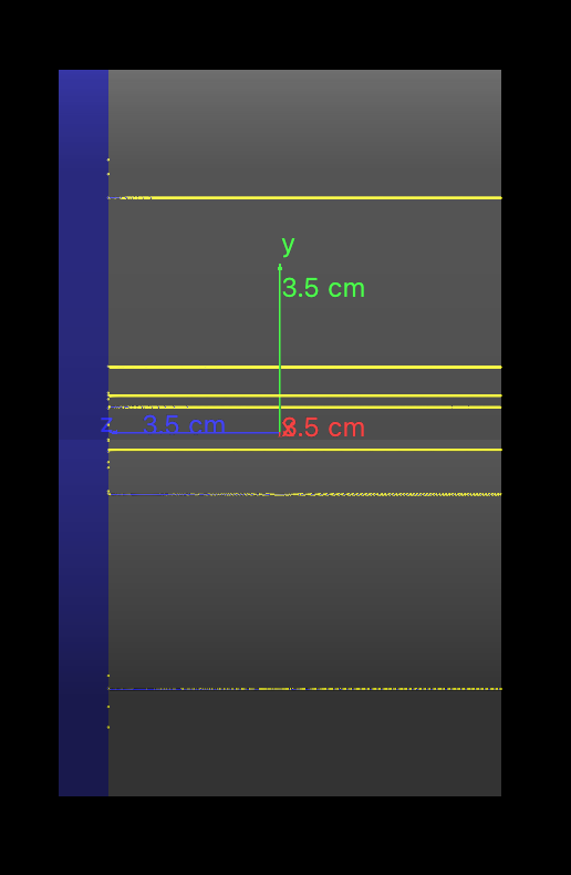
To fault find I’m using G4UniformElectricField as a control and adjusting the G4ElectricField to a similar uniform field. I’ll let you know how I get on.
I adjusted my COMSOL generated field to mimic the G4UniformElectricField and am importing it into PurgMagTabulatedEField3D and it’s behaving identically to G4UniformElectricField after a bit of tweaking of fieldUnit so my COMSOL generated field isn’t right. Nuts!
Not sure what you mean. A vector has magnitude and direction, so it draws an arrow (or line) whose length is proportional to magnitude with the appropriate 3D direction. Do you mean you want to see just the magnitude? How would we represent that? Like a dose distribution? I’m not sure if the wisdom of doing that, but perhaps you could write a user vis action that draws boxes of different size and/or colour?
What we (SuperCDMS) get out of COMSOL for our mesh fields is the potential (voltage) at each point, which you can visualize as a heatmap (“dose distribution”). We get the electric field by computing the -gradient of that potential distribution.
I don’t think Geant4 could directly do the potential (not without some ugly work integrating the field vectors!). Maybe a combined figure for the field vector? Use a color map for the magnitude, and just draw small unit vectors for the direction (I’m picturing something like the CMB polarization maps).
I could also see writing a standalone Geant4 “executable” that simply instantiates the electric field object – no geometry, no generator, not even a run manager. Do nested loops to sample the field in a grid (calling G4Field::GetFieldValue() with the C-array interface), and dump x,y,z,Ex,Ey,Ez to your favorite N-tuple or just a CSV file. Now you can use your favorite plotting code (ROOT, matplotlib, whatever), but you’re getting the same information that G4 would be using, rather than the raw COMSOL.
“Not sure what you mean. A vector has magnitude and direction, so it draws an arrow (or line) whose length is proportional to magnitude with the appropriate 3D direction. Do you mean you want to see just the magnitude?”
Actually more of the resultant direction. The magnitude (in this case) is less of a consideration.
How would we represent that? Like a dose distribution?
No, not a scalar field. It was discussed earlier in this thread visualising the e-field is a bit of a hit-and-miss affair. I may be wrong here but it seems to me to be that each e-field vector is illustrated in space by it’s 3 components (Ex, Ey and Ez) this can get confusing and overwhelming (for me) and wonder whether it’s possible to display only the resultant vector at a point in space. Of course it is possible that /vis/scene/add/electricField is displaying only the resultant vectors and I can’t see the wood for the trees.
However, in an attempt to visualise the e-field more clearly I installed Octave and it borked my QT files and now G4 won’t compile (for QT). So I have to fix that issue before I continue.
Meanwhile I had a chat to the local COMSOL guy (top class support from COMSOL) and we compared the generated file with the original field in COMSOL and all seems correct but I’m still seeing this peculiar wafting about of my primaries which isn’t apparent when I change the COMSOL field to a uniform field.