Sorry @allison how should I use this command?
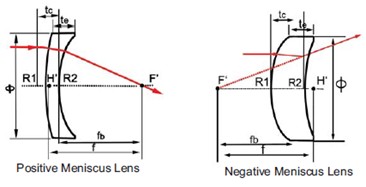
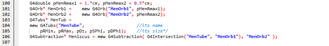
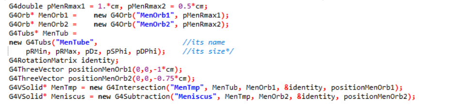
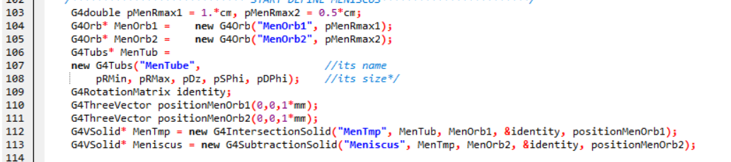
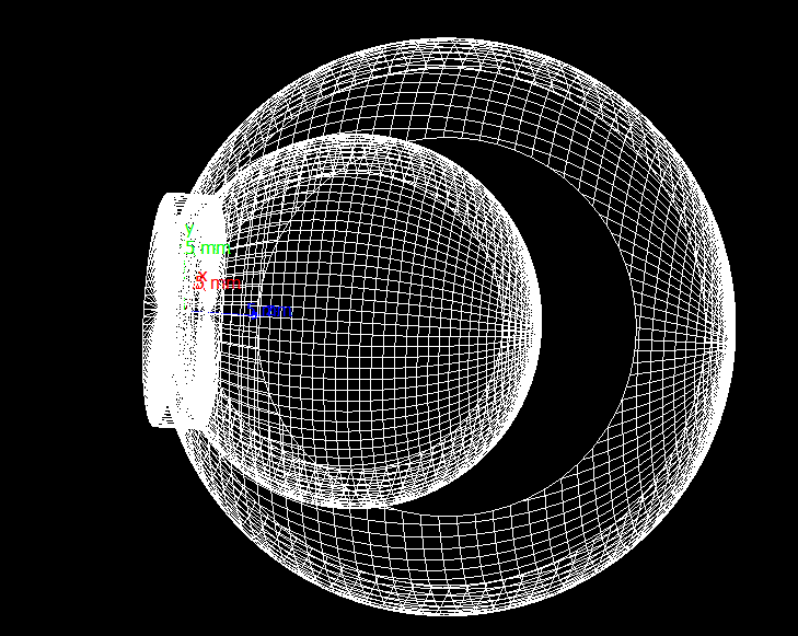
This is my Boolean solid definition
G4double pi = 3.14159265358979323846;
G4double pRMin = 0., pRMax = 0.75*cm, pDz = 1.5*mm, pSPhi = 0., pDPhi = 2*pi;
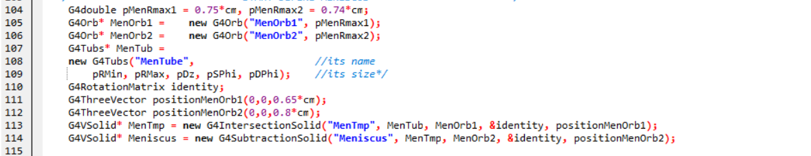
G4double pMenRmax1 = 0.75*cm, pMenRmax2 = 0.74*cm;
G4Orb* MenOrb1 = new G4Orb("MenOrb1", pMenRmax1);
G4Orb* MenOrb2 = new G4Orb("MenOrb2", pMenRmax2);
G4Tubs* MenTub =
new G4Tubs("MenTube", //its name
pRMin, pRMax, pDz, pSPhi, pDPhi); //its size*/
G4RotationMatrix identity;
G4ThreeVector positionMenOrb1(0,0,0.65*cm);
G4ThreeVector positionMenOrb2(0,0,0.8*cm);
G4VSolid* MenTmp = new G4IntersectionSolid("MenTmp", MenTub, MenOrb1, &identity, positionMenOrb1);
G4VSolid* Meniscus = new G4SubtractionSolid("Meniscus", MenTmp, MenOrb2, &identity, positionMenOrb2);
G4LogicalVolume* logicEnv =
new G4LogicalVolume(Meniscus, //its solid //solidEnv
env_mat, //its material
"Meniscus"); //its name
G4LogicalVolume* logicEnv2 =
new G4LogicalVolume(Meniscus, //its solid //solidEvn2
env_mat, //its material
"Meniscus2"); //its name
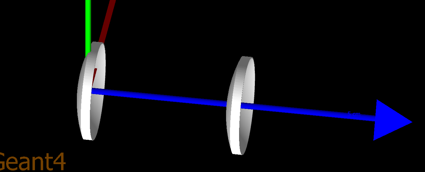
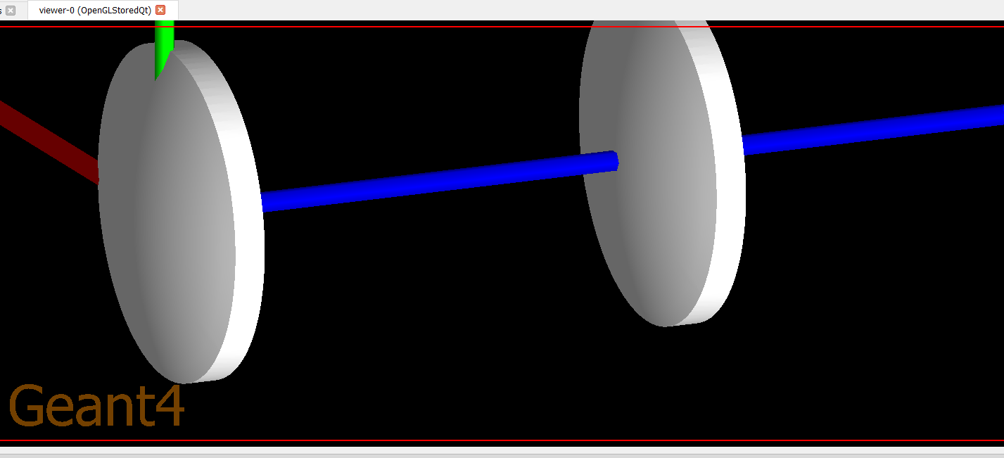
new G4PVPlacement(0, //no rotation
G4ThreeVector(), //at (0,0,0)
logicEnv, //its logical volume
"Meniscus", //its name //Envelope
logicWorld, //its mother volume
false, //no boolean operation
0, //copy number
checkOverlaps); //overlaps checking
new G4PVPlacement(0, //no rotation
G4ThreeVector(0,0,2.3*cm), //at (0,0,2.15) 2.15= 0.15*cm+2*cm
logicEnv2, //its logical volume
"Meniscus", //its name //Envelope2
logicWorld, //its mother volume
false, //no boolean operation
0, //copy number
checkOverlaps); //overlaps checking
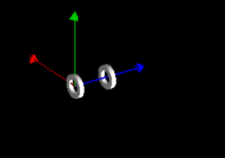
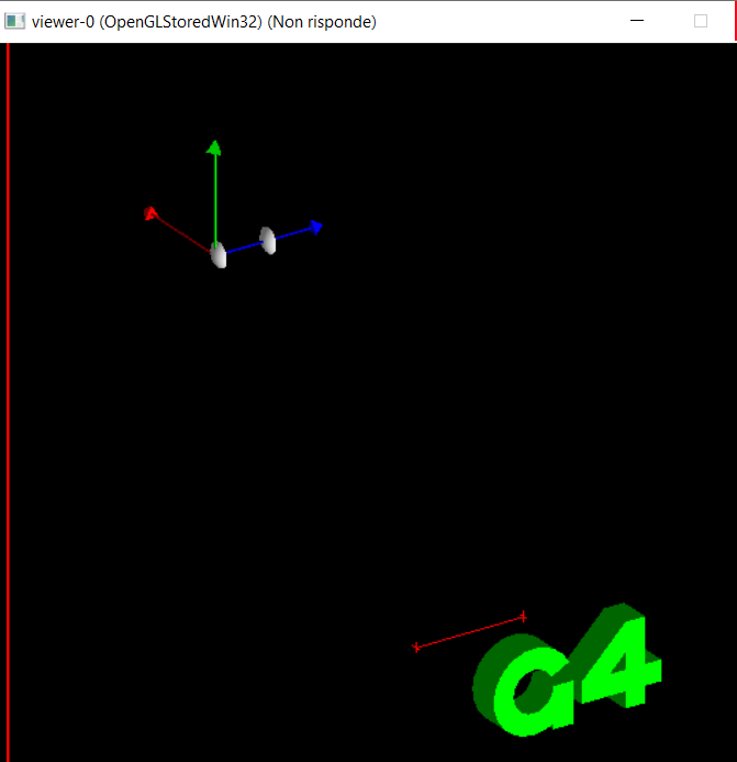
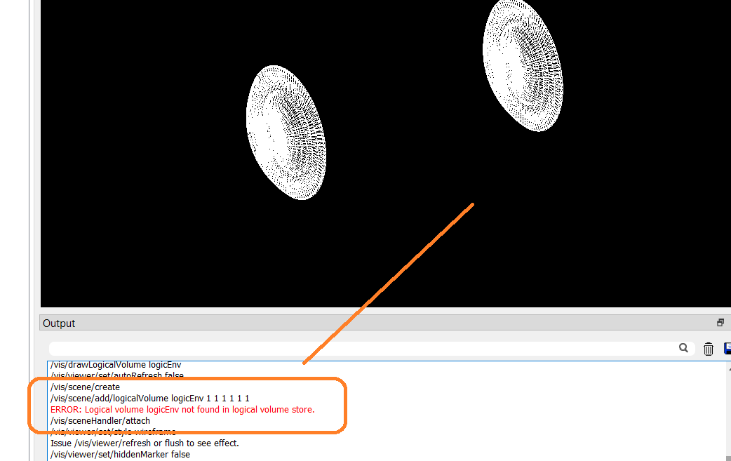
but if I write in the vis.mac the command
/vis/drawLogicalVolume logicEnv
/vis/drawLogicalVolume logicEnv2
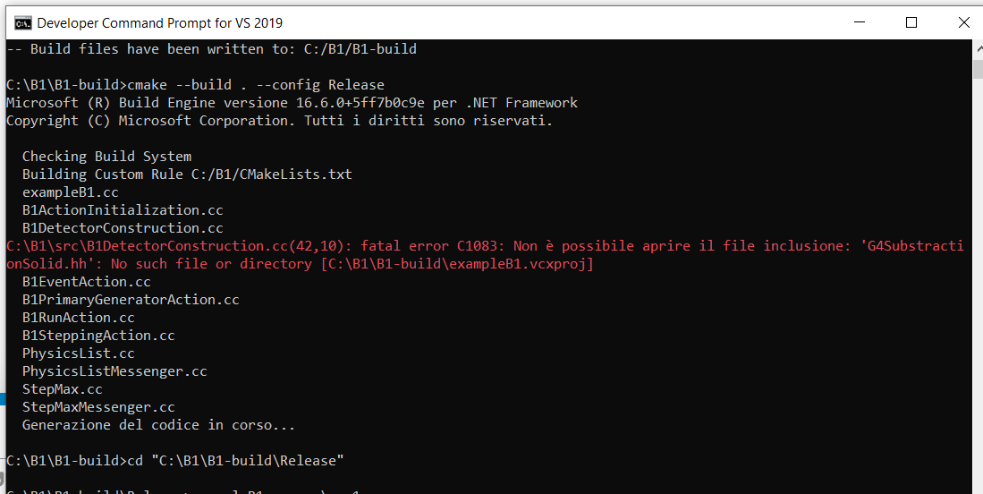
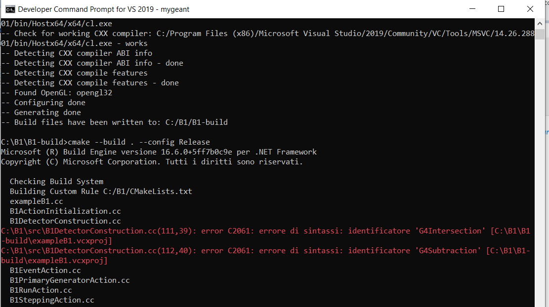
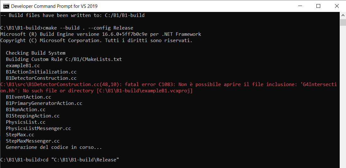
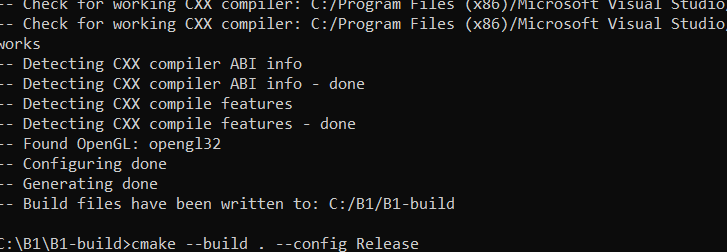
I get this error
and a similiar one for the loginEnv2