I am simulating the dose deposited in a water phantom by a (already validated) 6MV medical linear accelerator. Up to now, I was using the command-based scoring, but since I want to personalize my scoring in the future, I recently changed to Multi Functional Detector.
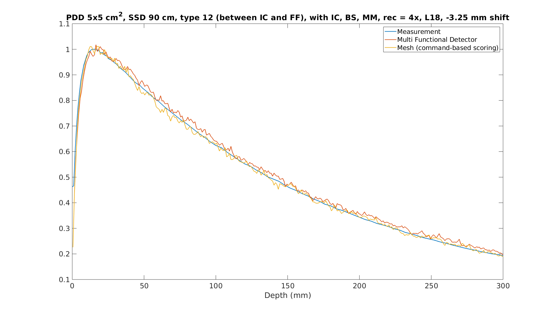
The problem is that the results (for dose deposited in a water phantom) obtained with the command based scoring and the Multi Funcional Detector are quite different (provided everything else - including the seeds - is exactly the same for both simulations). With the command-based scoring, the simulated curve follows the measured curve (which is our reference), while the Multi Functional Detector simulated curve does not match the measured data (I have data with better statistics, but for some reason, I was not able to upload here, and it is even clearer that one curve matches the measurements and the other doesn’t ).
I have checked the geometry several times, I can not find the source of these discrepancies, and neither can I determine which result should I trust (the one from command-based or the one from Multi Functional Detector).
Does anyone have a clue and/or have experienced this problem before?
Can you describe the nature of your scoring volumes? Also if you shared some of the commands you used for command based scoring and for MFD detector scoring that would be useful to evaluate the issue. For MFD scoring, are you extracting information from a physical detector or in a non-physical parallel world?
Hi,
Note for exactly the same mesh bins between two methods. When you define a mesh, it creates virtual detectors in the region of interest and it may be due to additional scattering or absorption in the command-based method.
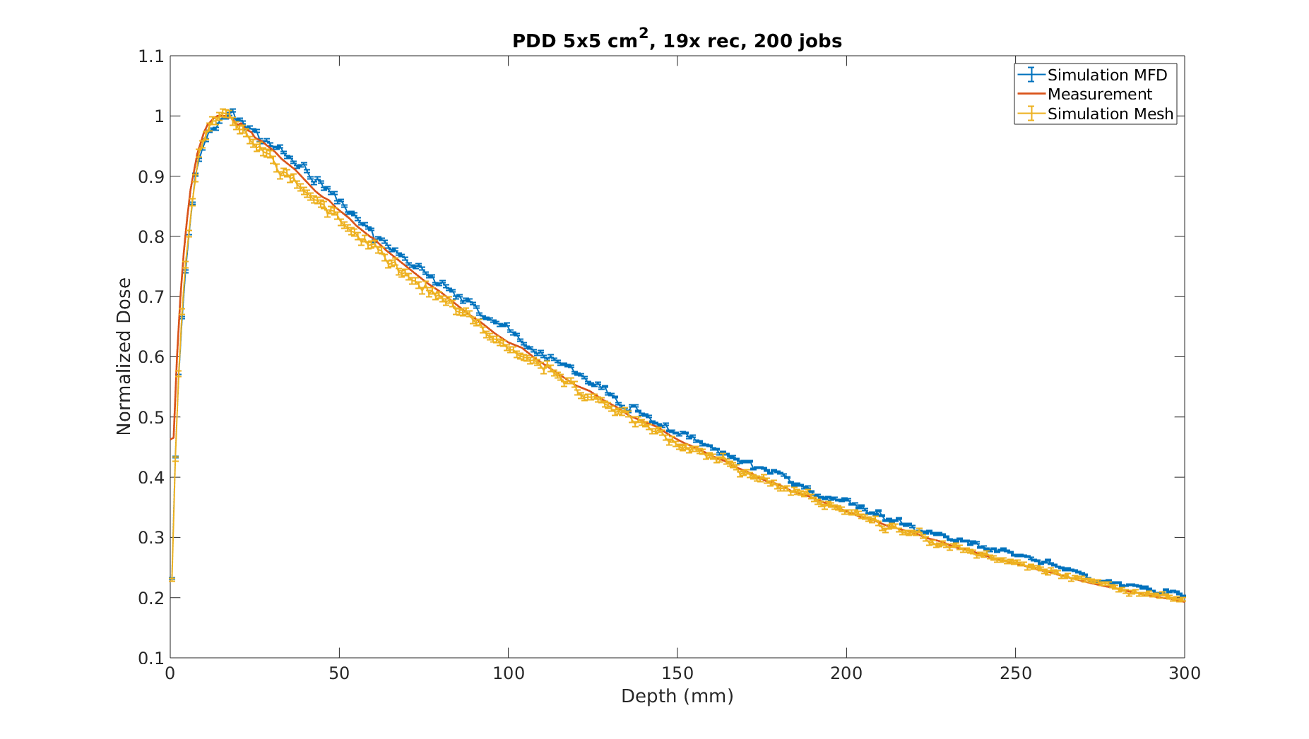
Dear @bmorgan thank you for your reply. I have performed another simulation with more statistics. For the command-based scoring (“mesh”), the relative error is withing 1.5% for the entire region; for the Multi functional detector (MFD), the relative error is within 0.5 %. I also checked the percentage difference between both simulations [100*(mesh-MFD)/mesh], and they are eu to 8% in some points, 3.5% in average. Here is the new simulation figure with uncertainty.
The command-based scoring ("mesh) is a column-like solid, divided into 300 voxels, positioned inside a water phantom (a normal solid, no overlaping occurs since the command-based is a parallel world).
For the MFD, I create a physical detector (same dimension as the mesh described above), positioned in the same place inside a water phantom. To avoid overlaping problems, I create the water tank as a solid with a hole inside, to accomodate the physical detector perfectly (which is also made of water, as I am interested in the dose deposited in water - same material and density as the water phantom).
The commands for MFD: are basically the ones used in the DICOM example, I just created a new scorer (Dose deposited^2, which I am also interested for statistical purposes). To record dose, I used the primitive scorer G4PSDoseDeposit3D. To construct the solid, I created my own .g4dcm defining the object as I wanted:
10 (# of elements)
0 Air (elements and tags)
1 LungInhale
2 LungExhale
3 AdiposeTissue
4 Breast
5 Water
6 Muscle
7 Liver
8 TrabecularBone
9 DenseBone
1 300 1 (number of voxels in x, y and z)
-2.5 2.5 (extension in x)
-200.0 100.0 (extension in y)
-2.5 2.5 (extension in z)
5 (300 times, corresponding to the material of the voxels to be created)
1.00 (300 times, corresponding to the density of the voxels to be created)
I am not sure I get what you mean. When I use the command-based scoring, a detector is created in a parallel world, which does not interfere in the water phantom geometry. When I use the MFD however, it is a physical solid and the radiation will make a step in each voxel boundary (which does not occur for the command-based scoring voxels). Is this correct?
I am aware of this difference, but since the solid created with the MFD has exactly the same material and density as the water phantom, I would expect it to behave like the original “full” water phantom.
Hi @juliana_martins, Some thoughts which may or may not prove helpful:
1.) Looking at the plot it looks like the shape of your PDDs fundamentally agree but the blue MFD curve appears to be shifted by a few mm. Where this is coming from I’m not sure.
2.) Regarding scoring: I would strongly encourage modifying your code to perform scoring in a parallel world. How are you creating a water tank with the hole inside? My intuition is that performing scoring in the physical world and having to subtract the scoring regions from the water tank is at least part of this discrepancy. If you accidentally introduce ~2-5 mm of air because of the geometry methods it would completely explain this discrepancy.
The people who develop Geant4 geometry code can speak to this much better, but I think from an optimization standpoint it is definitely not most efficient to introduce a boundary in your physical world between the non-scoring water region and scoring water region (i.e. the navigator has to process your particle crossing an artificial boundary, slowing things down). It may even be possible that something about the way particles are handled at the boundary is introducing the discrepancy.
3.) DICOM example: I see in the readme file that G4RegularNavigation is being used by default in the example. It also states that G4PSDoseDeposit_RegNav is required to be used when using these methods. Have you disabled G4RegularNavigation before using G4PSDoseDeposit3D as you stated?