Energy Deposition on the Boundary of World and Target Volume

My Source Code

I’ve been playing with the microelectronic example that came along with the geant4 package. I am using the original geometry from the microelectronics example, however, I shifted the example to the positive x-axis just to make my analysis process more convenient.

My Question

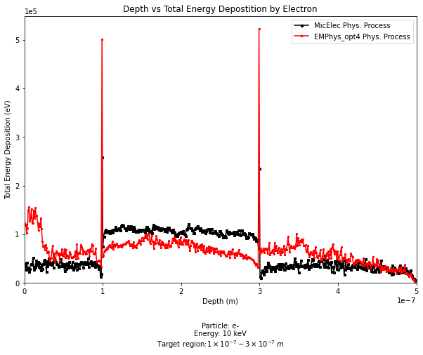
After firing 10,000 e- particles with energy 10 keV towards the target, I wrote the data into a CSV file and analyse them accordingly with python. Where I’ve noticed that at the boundary between the world and the logical target there seems to be something that is causing the energy of the electron deposited to be significantly larger than the other areas.

I then tried again with another physics list, and I seem to get the same result. (Please see the graph below)

Can anyone please point out what could be possibly causing this?

Are you recording the energy deposit at the post-step point? In reality, the “energy deposit” of a step really includes energy that was lost all the way along the step’s trajectory. Depending on your geometry, this could make a substantial difference in the energy/depth profile.

2 Likes

I am using the data I get from the GetTotalEnergyDeposit() method under the G4Step class to fill a CSV file. Could that be what is causing the problem?

G4Step::GetTotalEnergyDeposit() is correct. But I will bet that you are assigning that value to a single point, either the post-step point or the pre-step point. Right? In fact, that GetTotalEnergyDeposit() should be spread out along the whole line from the pre-step point to the post-step point.

1 Like

I am not sure what exactly do you mean by spreading that out across the whole line from the pre-step point to the post-step point. It would be nice if you would like to point out the changes in an example. My current code goes something like this, (the line of interest is near the bottom)

void SteppingAction::UserSteppingAction(const G4Step *step)
{
  G4double flagParticle = 0.;
  G4double flagProcess = 0.;
  G4double x, y, z, xp, yp, zp;
.yada
.yada
.yada
if (step->GetPostStepPoint()->GetProcessDefinedStep()->GetProcessName() != "Transportation")
  {
    x = step->GetPreStepPoint()->GetPosition().x() / nanometer;
    y = step->GetPreStepPoint()->GetPosition().y() / nanometer;
    z = step->GetPreStepPoint()->GetPosition().z() / nanometer;
    xp = step->GetPostStepPoint()->GetPosition().x() / nanometer;
    yp = step->GetPostStepPoint()->GetPosition().y() / nanometer;
    zp = step->GetPostStepPoint()->GetPosition().z() / nanometer;

    // get analysis manager
    G4AnalysisManager *analysisManager = G4AnalysisManager::Instance();

    // fill ntuple
    analysisManager->FillNtupleDColumn(0, flagParticle);
    analysisManager->FillNtupleDColumn(1, flagProcess);
    analysisManager->FillNtupleDColumn(2, x);
    analysisManager->FillNtupleDColumn(3, y);
    analysisManager->FillNtupleDColumn(4, z);
    analysisManager->FillNtupleDColumn(5, step->GetTotalEnergyDeposit() / eV);
    analysisManager->FillNtupleDColumn(6, std::sqrt((x - xp) * (x - xp) + (y - yp) * (y - yp) + (z - zp) * (z - zp)) / nm);
    analysisManager->FillNtupleDColumn(7, (step->GetPreStepPoint()->GetKineticEnergy() - step->GetPostStepPoint()->GetKineticEnergy()) / eV);
    analysisManager->AddNtupleRow();
  }
}

There’s no great way to do this “properly” with changing your N-tuple structure and your analysis code. It’s not a coding issue, it’s a physics issue. You will need to come up with an approach that meets your own analysis needs.

Let me try to describe the conceptual problem a bit differently. Think about what the “actual particle” is doing as it traverses your volume. As it moves through the material, it is continuously losing energy, a little bit at a time (this is why we call it “dE/dx”, energy loss per unit length). Geant4 takes the particle’s trajectory and breaks it into steps. For each of those steps, Geant4 “integrates” dE/dx along the step, and gives you that total as “GetTotalEnergyDeposit()”. But that energy wasn’t all deposited at a point (your (x,y,z) coordinates in theN-tuple.

1 Like

The problem as I understand it is that these steps as @mkelsey described are forcefully terminated at each volume boundary, hence the peaks at these positions!?

I have seen the approach (e.g., here: examples/advanced/microbeam/src/SteppingAction.cc · geant4-10.7-release · geant4 / geant4) to randomize the “deposition location” uniformly within the pre and post step point, something along the lines

x = step->GetPreStepPoint()->GetPosition().x() / nanometer;
y = step->GetPreStepPoint()->GetPosition().y() / nanometer;
z = step->GetPreStepPoint()->GetPosition().z() / nanometer;
xp = step->GetPostStepPoint()->GetPosition().x() / nanometer;
yp = step->GetPostStepPoint()->GetPosition().y() / nanometer;
zp = step->GetPostStepPoint()->GetPosition().z() / nanometer;

G4double r = G4UniformRand(); // should be 0..1
...
analysisManager->FillNtupleDColumn(2, x+r*(xp-x));
analysisManager->FillNtupleDColumn(3, y+r*(yp-y));
analysisManager->FillNtupleDColumn(4, z+r*(zp-z));
...

would that make sense for your analysis?

edit: with better readability:

G4ThreeVector randomPosition = step->GetPreStepPoint() + G4UniformRand()*(step->GetPostStepPoint() - step->GetPreStepPoint());
...
analysisManager->FillNtupleDColumn(2, randomPosition.x()/nanometer);
analysisManager->FillNtupleDColumn(3, randomPosition.y()/nanometer);
analysisManager->FillNtupleDColumn(4, randomPosition.z()/nanometer);
...
1 Like

That’s correct (and always correct). Steps always stop at volume boundary (with G4StepStatus == fGeomBoundary).

I like your method of choosing a random point within the step, but it may still produce an artificial peak in the user’s plot.

1 Like

In TestEm11, SteppingAction :
//longitudinal profile of deposited energy
//randomize point of energy deposotion
//
G4StepPoint* prePoint = step->GetPreStepPoint();
G4StepPoint* postPoint = step->GetPostStepPoint();
G4ThreeVector P1 = prePoint ->GetPosition();
G4ThreeVector P2 = postPoint->GetPosition();
G4ThreeVector point = P1 + G4UniformRand()(P2 - P1);
if (step->GetTrack()->GetDefinition()->GetPDGCharge() == 0.) point = P2;
G4double x = point.x();
G4double xshifted = x + 0.5
fDetector->GetAbsorSizeX();
analysisManager->FillH1(1, xshifted, edep);

1 Like

I know this is an old topic but I am running into a similar issue. My geometry is thin films with layers as little as 0.7 nm and up to 60 nm. I have looked at reducing the step size to force more frequent energy deposition, but I think that this method might work.

Do we think that it would be more accurate to deposit the energy at a single random point between pre-step and post step point, or do spread the energy out evenly over each bin between the pre and post step points?

Please don’t revive old topics. If you’ve got a specific question for you application, could you create a new topic? Thank you!