Help on creating collimator with a hole

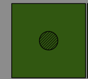
I want to create a simple neutron collimator. This is what I want a solid borated polythene made of 30x30x3cm, then a pinhole in the middle. like the picture I have attached. I used this code from the threads here to create it but I get errors and it doesnt look like what I like. Can anyone help me out? this is the code I used.

“”
//The Borated polythylene_block1 with pinhole

BoratedSize = 30cm;
Borated_thickness = 3
cm;
Borated_Box1 = new G4Box(“Borated1”, //its name
BoratedSize/2,BoratedSize/2,Borated_thickness/2); //its dimensions

Hole = new G4Box(“BoxHole”, //its name
5cm/2,5cm/2,3*cm/2); //its dimensions

collimator = new G4SubtractionSolid(“collimator”,
Borated_Box1, //its logical volume
Hole, //its mother volume
0,
G4ThreeVector(0cm,0cm,0*cm)
); //copy number

Borated_LV1 = new G4LogicalVolume(collimator, //its shape
b_polyethylene, //its material
“Borated1”); //its name

Borated_PV1 = new G4PVPlacement(0, //no rotation
G4ThreeVector(0cm,0cm,21.5*cm), //at (0,0,0)
Borated_LV1, //its logical volume
“Borated1”, //its name
fLBox, //its mother volume
false, //no boolean operation
0,true); //copy number

G4VisAttributes* green = new G4VisAttributes(G4Colour::Green());

green->SetVisibility(true);
green->SetForceAuxEdgeVisible(true);

Borated_LV1->SetVisAttributes(green);

“”

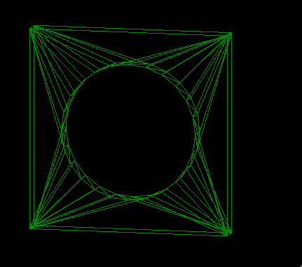
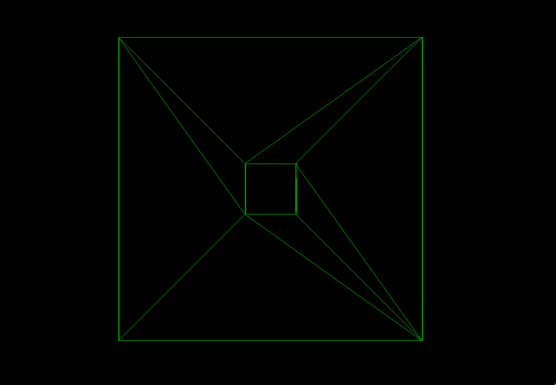
and this is what I have when I visualized it.

Screenshot from 2024-03-11 13-16-46

Geant4 Version: geant4-v11.1.3

_Operating System: Ubuntu 20.04.6 LTS
_Compiler/Version: c++
_CMake Version: VERSION 2.6 FATAL_ERROR

If you want a circular pinhole, create a cylinder with G4Tubs instead of a box

Screenshot from 2024-03-11 13-44-14
with your suggestion I have this. I think I do not understand where the lines are also coming from.

The lines are a visualization artifact; they are showing you the tesselated shapes used to draw the object. when you specify “wireframe”. If you specify “surface” visualization, then you’ll get something more like what you imagine.

okay this is my vis.mac
“”

/run/initialize
/vis/open OGL
/vis/viewer/set/viewpointVector 1 1 1
/vis/drawVolume
/vis/viewer/set/autoRefresh true
/vis/scene/add/trajectories smooth
#/vis/scene/add/scale 10 cm
#/vis/scene/add/axes
/vis/scene/add/eventID
/vis/scene/endOfEventAction accumulate 1000000000
#/gun/particle neutron
/vis/ogl/set/displayListLimit 1000000000
#/run/beamOn 1000000
“”
I did not specify anything but I was worried it was a problem. if its just the visualization then i am ok now. Thank you all for your help.

You’re welcome. The command you can use is

/vis/viewer/set/style surface

(put it with the viewpointVector line).

Instead of using G4SubtractionSolid, I would put a daughter of air inside.

Please could you explain it a little bit. what will be the difference and how can I do that?. Thank you

okay I try that. Thank you

Well, given a volume, if you place a daughter of a different material inside, the daughter’s material displaces the mother’s. This is a 50-year GEANT convention. So just place a G4Tubs daughter with +/-z surfaces coincident with the relevant mother’s surfaces, The coincident surfaces will look opaque in surface-style visualisation, but you will see a simple picture in wireframe, without all those connecting lines, and the zero-thickness surface will not be a problem for tracking. Plus, it’s faster CPU-wise.

okay thank you very much I will try that.

This topic was automatically closed 7 days after the last reply. New replies are no longer allowed.