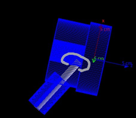
How to use Boolean Solid for cutting this part of geometry in picture?
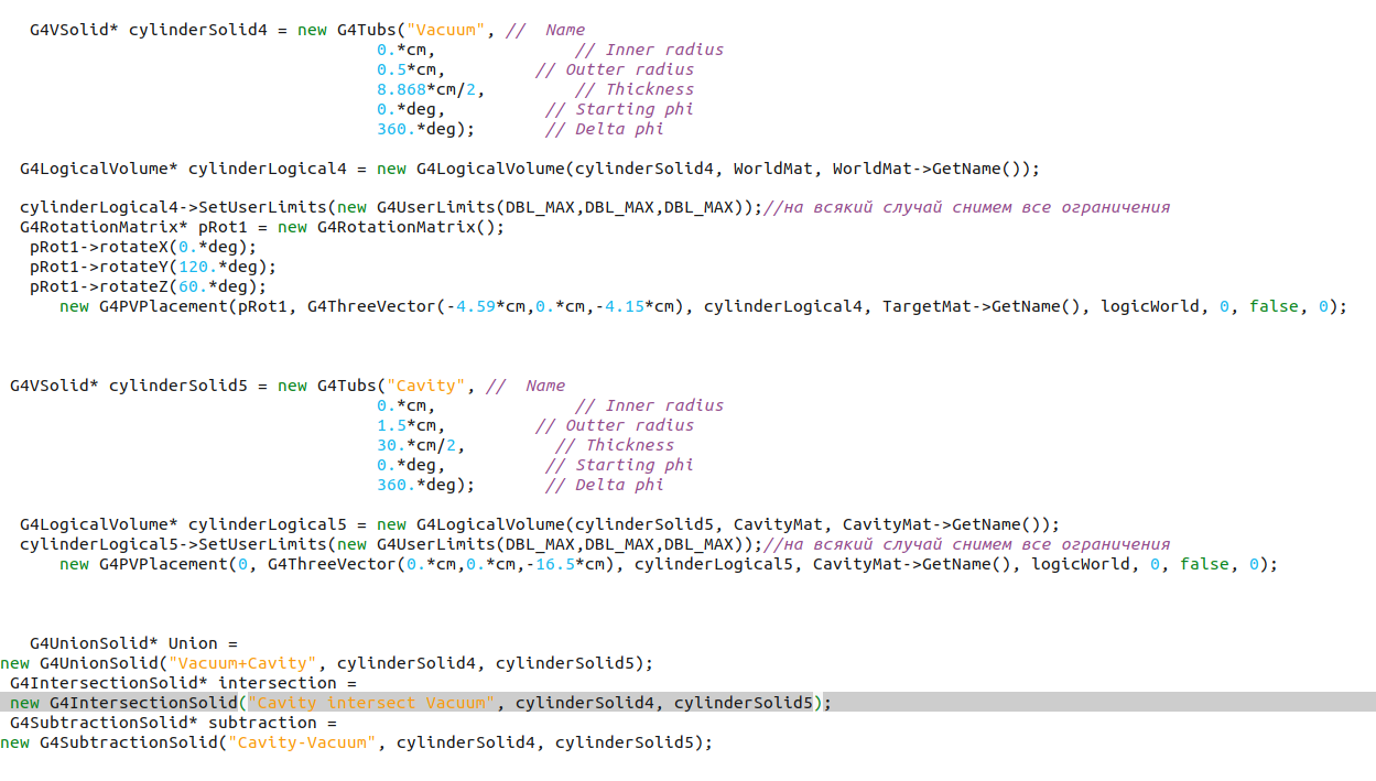
I made it like this but, doesn’t work:
G4UnionSolid* Union =
new G4UnionSolid(“Vacuum+Cavity”, cylinderSolid4, cylinderSolid5);
G4IntersectionSolid* intersection =
new G4IntersectionSolid(“Cavity intersect Vacuum”, cylinderSolid5, cylinderSolid4);
G4SubtractionSolid* subtraction =
new G4SubtractionSolid(“Cavity-Vacuum”, cylinderSolid4, cylinderSolid5);
White cylinder is Vacuum (cylinderSolid4), and blue is Cavity (cylinderSolid5)…
As a result of looking at your GDML model wondering if you have any spare time to look at some enhancements to our FreeCAD GDML workbench https://github.com/KeithSloan/GDML
Thanks to some great work by Munther Hindi in implementing a suggestion of mine it now supports creating GDML Models from Extruded and Revolve FreeCAD Sketches see
As it involves a lot of new code it is currently available in the beta2 branch rather than the main branch.
We would be really interested in any feedback and would like to know if it made creating your model any easier etc.
Creating a Boolean solid in Geant4 requires two solids and a transformation for the second solid. The transformation specifies the position of the second solid relative to the first one, in your case it is necessary.
There is no transformation in the parameters of the Boolean operations in your code.
Below is what has been done in your code:
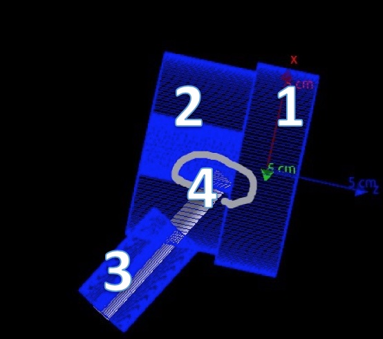
Construction of a solidcylinderSolid4
Construction of a logical volumecylinderSolid4
Construction of a physical volume (first G4PVPlacement, no rotation)
Construction of a solidcylinderSolid5
Construction of a logical volumecylinderSolid5
Construction of a physical volume (second G4PVPlacement, no rotation)
Construction of a solidUnion (cylinderSolid4 + cylinderSolid5, no transformation)
Construction of a solidintersection (cylinderSolid5 - cylinderSolid5, no transformation)
Construction of a solidsubtraction (cylinderSolid4 ^ cylinderSolid5, no transformation)
Last three solids have not been used to construct any logical and physical volumes, so they will not participate in the simulation and even will not be seen at visualisation.
As result there will two solids, solid1 and solid234, which should be used to create logical volumes (assigning material) and then physical volumes (placement logical volumes in the World volume)