Need advice how to create Hexagonal prism

Hello all!

I would like to create a geometry object - “Hexagonal prism”. Unfortunately, it is non-standard solid in GEANT4. I have found that for ATLAS project somebody suggested using the G4ExtrudedSolid object to create a similar structure.

Could somebody give an example or a clear explanation of how to create such objects? Triangular prism, pentagonal prism are interesting too…

You can find an example of how to create a “Hexagonal prism” using G4ExtrudedSolid, G4Polyhedra and G4TessellatedSolid in the Geant4 benchmark test ..source/geometry/benchmarks/benchRightPrism.cc.

Below is the code for G4ExtrudedSolid:

const G4int nsect = 6;
std::vector<G4TwoVector> polygon(nsect);
G4double ang = twopi/nsect;
for (G4int i = 0; i < nsect; ++i)
{
  G4double phi = i*ang;
  G4double cosphi = std::cos(phi);
  G4double sinphi = std::sin(phi);
  polygon[i].set(rmax*cosphi, rmax*sinphi);
}
                                                                                               
G4TwoVector offsetA(0,0), offsetB(0,0);
G4double scaleA = 1, scaleB = 1;
G4VSolid* xtru = new G4ExtrudedSolid("Extruded", polygon, dz, offsetA, scaleA, offsetB, scaleB);

Triangular and pentagonal prisms can be created in a similar way, just setting nsect = 3, or nsect = 5

Sorry, Geant4 benchmarks and tests are not distributed in public releases, so I attach benchRightPrism.cc here. Please see it, if you are interested in alternative ways to create “prismoid” objects.
benchRightPrisms.cc (43.5 KB)

Thank you very much for your comprehensive answer!

Good day!

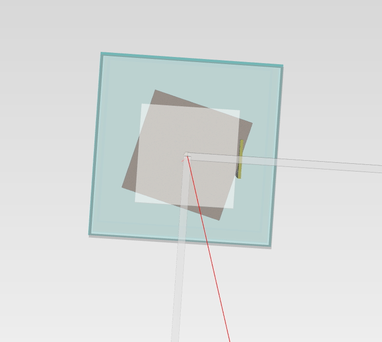
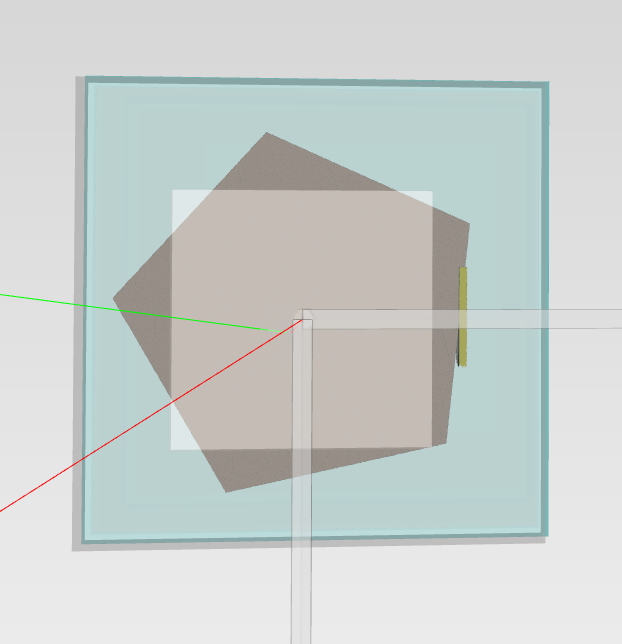
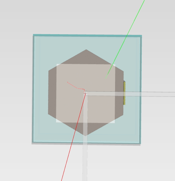
I have found a strange issue with G4Extruded solid. I generated 3,4,5,6-angle prisms (scintillator) with the Radius 7.5mm. The 4,5 -angle prisms demonstrated clearly visible distortion when I generated a VRML scene to check how it looks. Please see the images…

I used exact code like yours:

const G4int nsect = 3; //3,4,5,6
std::vector<G4TwoVector> polygon(nsect);
G4double ang = twopi / nsect;
G4double dR = 7.5 * mm.;

for (G4int i = 0; i < nsect; ++i)
{
	G4double phi = i * ang;
	G4double cosphi = std::cos(phi);
	G4double sinphi = std::sin(phi);
	polygon[i].set(dR * cosphi, dR * sinphi);
}

G4TwoVector offsetA(0., 0.), offsetB(0., 0.);
G4double scaleA = 1., scaleB = 1.;
G4VSolid* solidScint1 = new G4ExtrudedSolid("Extruded", polygon, fScint1Thickness / 2, offsetA, scaleA, offsetB, scaleB);

Additionally, when I run “/geometry/test/run” command, it reports that there are overlapped volumes between my elements, and I see it on the distorted pictures. For 6-angle prism, all works fine!!

What can be wrong??? float->int rounding in some places???

Sincerely Yours,
Vyacheslav Porosev


It is difficult to investigate the issue without seeing the code where the model was constructed. The code that creates the prism looks OK, but the real position of the prism depends on the transformation that has been applied to it.

Concerning the overlaps. Again, it’s difficult to say anything definite without seeing the code, I can only make my own guess. I looks like there is an overlap between the prisms and and the “white box” in all images. As well as, in all images except the last one, there is an overlap between the prisms and “yellow bar”.

PS. BTW, to make it easier to place the prism, you may want to use “starting angle” when creating the prism, I mean:

G4double phi = i * ang + phiStart;

Assuming the first face of the prism (the first edge in the polygon) should be orthogonal to the X-axis, then phiStart should be -ang/2:

G4double phi = i * ang - 0.5*ang;

I am sorry that I waste your time. It was my stupid mistake with the transformation matrix of a physical volume.

It’s Ok, the forum is a place to ask questions and share various issues.

Hi, evc. I am troubled by creating an irregular polyhedron using G4Polyhedron. Do you have any example showing how to create an irregular polyhedron? Thanks a lot ! :grinning: :grinning: :grinning:

Hi! G4Polyhedron is not a G4VSolid, it can not be used for simulation. G4Polyhedron is a class that is used for visualisation. If you want to create a solid that is an irregular polyhedron, please use G4TessellatedSolid. An example of the G4TessellatedSolid construction is available in the header G4TessellatedSolid.hh.

Hello Evc,

Thank you a lot for your answers. It really helped. But I would like also to ask you some questions.
Forgive me if what I ask is too obvious but I just started with geant4 and I am still trying to read and understand all the documentation while building the geometry I want.

I would like to make a canonical hexagon inside an orthogonal shape.
So I defined the box, and then tried to place (for start) an hexagonal prism (G4ExtrudedSolid) as daughter volume into the box. I would like to have the same thickness as the box.
It runs without a problem but when I plot it I cannot see the hexagon, only the box.
What exactly is dR and dz? I do not know what number I have to put in order to see it.

auto detectorA
= new G4Box(“Detector”,
SizeXY/2, SizeXY/2, Thickness/2);

auto detectorB
= new G4LogicalVolume(
detectorA,
MaterialA,
“Detector”);

new G4PVPlacement(
0,
G4ThreeVector(0., 0., 0.),
detectorB,
“Detector”,
worldB,
false,
0,
fCheckOverlaps);

const G4int nsect = 6;
std::vector polygon(nsect);
G4double ang = twopi/nsect;
for (G4int i = 0; i < nsect; ++i)
{
G4double phi = iang;
G4double cosphi = std::cos(phi);
G4double sinphi = std::sin(phi);
polygon[i].set(dR
cosphi, dRsinphi);
}
G4TwoVector offsetA(0,0), offsetB(0,0);
G4double scaleA = 1, scaleB = 1;
G4VSolid
xtru = new G4ExtrudedSolid(“Extruded”, dz, offsetA, scaleA, offsetB, scaleB);

I am attaching you a part of the code. The sizeXY is 0.1*cm for now. And I want the hexagon to have the same thickness of the box.
Do I have to place the hexagon somehow in order to see it? Also the if I want to make many I do replica?
I think the extruded is the most easy way but what about if we had many strips to create the hexagonal shape would it be very complex for a number of shapes?

Thank you a lot and I apologise for the many questions.

Kind regards
Helen

Geant4 uses the following concepts in the description of a detector geometry:

  1. Solid. Solids have only shape (box, tube, extruded solid, …);
  2. Logical volume. Logical volume describes a volume’s full properties (material, magnetic field, …), except position. The same solid can be used in several logical volumes.
  3. Physical volume. Physical volume is created by placing a logical volume inside another logical volume. The same logical volume can be used in several physical volumes.

For more details please read the chapter “How to Define a Detector Geometry” in the “Book For Application Developers

Answering your questions:

  1. The hexagon should be used to create a logical volume, which then should be placed to its mother logical volume;
  2. It is not a problem to have a detector with few thousand volumes, nothing to worry.

I suggest that you also have a look at the example B1. It is a basic example that contains very simple detector, consisting of a box (“Envelope”) and two simple objects (“Shape1” - cone, “Shape2” - trd) inside it.

Thanks a lot! I have tried the method you mentioned. But I have met new exceptions:


-------- WWWW ------- G4Exception-START -------- WWWW -------
*** G4Exception : GeomNav1002
      issued by : G4Navigator::ComputeStep()
Track stuck or not moving.
          Track stuck, not moving for 10 steps
          in volume -World- at point (393460.9582879422,716420.7885916836,2611898.351485264) (local point (393460.9582879422,716420.7885916836,2611898.351485264))
          direction: (0,0,-1) (local direction: (0,0,-1)).
          Potential geometry or navigation problem !
          Trying pushing it of 1e-07 mm ...Potential overlap in geometry!

*** This is just a warning message. ***
-------- WWWW -------- G4Exception-END --------- WWWW -------

should I ignore the exceptions?

In principle you can ignore the warning message. But be sure that your detector looks like expected. From my point of view, there is something strange, the point where the problem has been reported has z-coordinate ~ 2.6 km

Thanks! before /run/beamOn, the output seems no overlaps:

Checking overlaps for volume Target ... OK!
Checking overlaps for volume Mountain ... OK!

And if I run it in graphical mode, the exceptions will not show up.

Be aware that when you are working with objects bigger than 2.5 km, the calculation error may easily exceed the half thickness of the surface, which is equal to 0.5 x 10^-9 mm in Geant4. This may occasionally confuse the navigation algorithm, which is designed to stop at the surface of an object and change current material.

Dear Helen,

For each object in the structure of your detector you should make three steps:

  1. Create a solid.
  2. Create a logical volume, by assigning a material to the solid.
  3. Create a physical volume, by placing the logical volume to its mother logical volume.

Please see how it was done in geant4.x.x.x/examples/basic/B1/src/DetectorConstruction.cc

In your code the solid xtru is not used. This is the reason why you don’t see it.
dR is the radius of the circumscribed circle around the polygon (which is a hexagon). A hexagon with dR = 0.2 mm will take less than half the area of a 1 mm x 1 mm square and will be cleary visible.

Thank you very much! The height of my object is about 4km.:joy:
I have another problem. Do you know how to draw a polygon facets? should I divide the polygon into triangular facets ?

Stricly speaking a polygon is a 2D object, it does not have facets. A 3D object bounded by plane facets is called a polyhedron. In Geant4 a polyhedron can be constructed using G4TessellatedSolid. The surface of a G4TessellatedSolid object already consists of triangular facets, there is no need to apply triangulation.

Relative triangulation. If for some reason you would like to make triangulation of a polygon, you can use G4GeomTools::TriangulatePolygon() to do so.