Performance issues for using many Boolean Solids from G4TesselatedSolids?

Hi there,

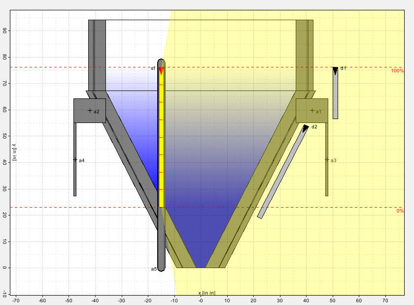
I am writing a web application for simulating radiometric measurement systems consisting of a tank filled with various liquids, gamma sources (possibly in curved dip tubes) and detectors mounted on the tank.

Since any of those things can be quite complex, I would like to use CAD models and import them as G4TesselatedSolid, e.g. by use of CADMesh.

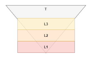
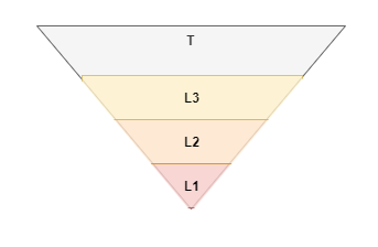
Now, since any of these components could be inside the tank and since there are multiple layers of liquids in the tank, I also need Boolean Solids, mainly subtractions, in order to avoid overlaps. For example, I would subtract the dip tube from the tank and all liquid layers, before placing the dip tube in the world volume. Likewise, I would subtract various tank walls from each other, in order to avoid numeric problems related to curvature discretization of the various CAD models and in order to to ensure water-tightness in the model.

As far as I understand it, any tracking for a Boolean Solid is done by executing the tracking for each operand and then applying the boolean operation on the results. How does that work with G4TesselatedSolid? Does that mean that all facets/triangles are involved in the boolean operation?

Is it, performance-wise, a bad idea to combine G4TesselatedSolid with Boolean Solids? Does anybody have any experience with this on a large scale with big CAD models and many boolean operations?

As a side note: This is a rather big project with a high degree of automation and I cannot foresee yet, how big the models and meshes involved can become.

1 Like

G4TesselatedSolid has an auxiliary internal structure that allows to perform calculations rather efficiently. So, to use it in Boolean Solids should not be a problem. However, I am not sure that Boolean Solids are absolutely necessary in your case. If you could provide a sketch drawing of your model, I would be in a better position to advise.

Thank you for your answer.
Here is an example for an application with a rod source s1 (yellow) inside a dip tube and two rod detectors d1 and d2 (grey) outside the tank.

The system I’m building is some sort of web service / HPC scheduler wrapper around Geant, so that users can run their simulations via a web GUI in the browser without having to write C++ code. Therefore, I do not know beforehand what sort of geometry they add.

From the picture you can see that we also need to support so-called “application items” like material blocks a1 to a4 which can overlap with other solids and need to be subtracted from them.

Also, like mentioned above, the tank will include multiple layers of different liquids from which the dip tube needs to be cut out. When the tank is not as simple as the one in the picture, these liquid layers cannot be defined in tank shape. I would rather define them as cuboids which I intersect with the tank interior.

Last, but not least, as mentioned, the different tank walls might not align perfectly, so I need to avoid overlaps there, too.

Ok, using Boolean solids looks reasonable. What is not clear for me, why do you want to define the liquid layers as the intersection of cuboids with the tank interior? Would it be easier to define the tank as a solid bounded by its external surface, and the liquid layers as the tank daughter volumes bounded by the tank internal surface?

@evc thank you so much for your valuable feedback. I have three follow-up questions

1.) I am new to Geant and not very familiar with the concept of mother and daughter volumes. I inherited the project from a colleague who always just used one single mother volume “world box” where he placed everything without having any sort of volume hierarchy. I guess that was okay, because until now our models were not really complicated. But this is changing now.

I always assumed that a daughter volume’s dimensions must not exceed the mother volume’s boundaries (aka surface). Your answer suggests that the liquid layers would be clipped by the tank internal surface when placed as daughter volume. Is that correct or did I misunderstand that?

So can I place the cuboids L1, L2, L3 as daughter volume in the conical mother volume T:
image
and then end up with this?
image
Did I understand you correctly?

Because my problem is, that even when I do have a (possibly complicated, tesselated) tank internal surface, I need a way to “fill it” vertically with liquid.

2.) I also have a question about the intersects, e.g. for the dip tube a5 in my original drawing. Since the dip tube penetrates both tank walls and liquids, I was wondering how the relationship between solids, logical volumes and physical volumes is when it comes to boolean subtractions. The subtraction operation is applied to solids. But can I subtract a solid from other solids that will end up in different logical and/or physical volumes (and which might also have different mother volumes) from each other? How would the placement work and what would be the order of operations?

So assuming, I did model the liquid layers as daughter volumes of the internal tank volume, then the internal tank volume, the tank walls, and the dip tube would be placed in the world volume. However, the dip tube would have to be subtracted from everything.

3.) I have some objects, like, e.g. the detector, that could be inside the internal tank volume, or outside the internal tank volume or both, when the tank is open at the top and the detector is located at the tank edge. So the detector’s mother volume probably could/should not be the internal tank volume. I assume in that case I will have to place the detector in the world box and boolean subtract it from the tank interior. Is that right?

1.) No, you misunderstood, daughter volumes should not extend beyond the boundaries of the mother volume.

In my reply I meant that in the hierarchical approach, the tank can be defined as a volume bounded by its outer surface, but the inner surface can be used to define the liquid layers. Taking into account that the bottom and top surfaces of the layers are horizontal planes it should not be too difficult. In case if the tank has a circular cross-section, G4Polycone can be convenient for this.

2.) As you correctly written Boolean operations are applied to Solids - objects that do not yet have a material. Same Solid can be used in several Logical Volumes, which may have different materials. So, there is no problem to subtract the dip tube Solid from several other solids.

BTW, applying subtraction is not the only option. For example, let consider a simple case where there is just one liquid. Then the hierarchy of volumes can look like the following:

  • level 0: the World volume
  • level 1: the tank, a volume defined as a union of a solid bounded by the outer surface of the tank and the dip tube;
  • level 2: the liquid, a volume defined as a union of a solid bounded by the inner surface of the tank and the dip tube;
  • level 3: the dip tube

3.) The detector can be defined at any level of the hierarchy, not only in the World.

@evc wrt your feedback:

1.) Thank you for clarifying. I agree in the case of rotational symmetry. However, when a tank is given by some (at compilation time unkown) CAD model, I would not know how to generate the liquid layers dynamically without using boolean solids Unless, you have another helpful advice.

2.) That is an interesting approach. Thank you for pointing me in this direction.

3.) The problem here is that at compilation time I do not know which mother volume (or hierarchy level) the detectors will belong to. And what would I do, if used the approach that you proposed in 2.) and a detector would be half-way inside the tank and half-way outside the tank?
If I knew that at compilation time, no problem. I could just adjust the hierarchy accordingly. But the geometry specs for my use case will only be available at runtime.

and a detector would be half-way inside the tank and half-way outside the tank?

You may find the following helpful. When constructing your model, some details of the model, that are actually whole, can be intentionally be subdivided into parts for convenience of the construction.

Hi Joerg

Have a look at Parallel Geometries — Book For Application Developers 11.0 documentation. This allows overlapping volumes. Volumes in a layered mass geometry, if supplied with material, take precedence over lower layers. Thus, perhaps, your “detector … half-way inside the tank and half-way outside the tank” could be a volume in an upper layer.

John

Hi @Joerg .

I see you are making quite a nice progress on the Web application with Geant4 backend. I am not working on a similar project and have some prototypes. I would be glad to have some technical discussion (i.e. via Zoom videoconference) on these issues. Can you drop me an email at Leszek.Grzanka@cern.ch ?

Cheers,
Leszek

Hi

A few days ago I posted a message about Parallel Geometries — Book For Application Developers 11.0 documentation. Did you try it? Is it not useful to you?

John