Here, we consider incident unidirectional and monoenergetic electron beams on the benchmark of Rogers and Mohan: water-bone-lung-water.
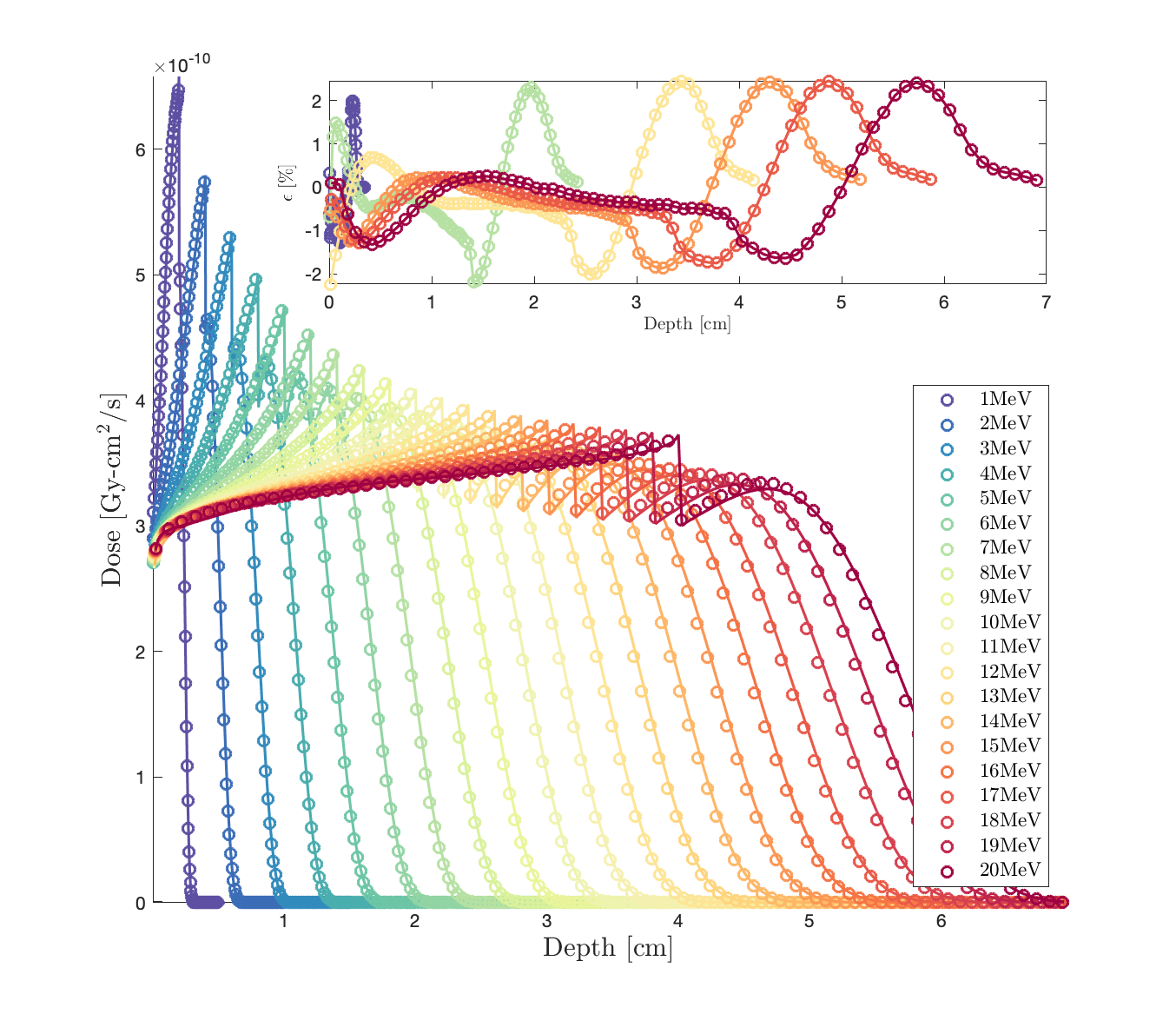
We compare the 1D dose depth profile of Geant-4 (circles) vs. Dragon-5 (solid lines). Dragon-5 is a deterministic Boltzmann-Fokker-Planck solver for nuclear reactor design and safety analysis. Fig.1. shows the dose around the bone slab.
The dose predicted by Geant-4 (G4EmLivermore Physics List) at the bone interface is not correct (obviously, not physical). Choosing another PhysicsList (e.g. G4EmPenelope) will move this incorrect behaviour of Geant-4 elsewhere. Moreover, we can see that the problem appears at higher energies. I have two questions. 1) Could you explain to us what physically causes such a failure at the interface ? 2) how Geant-4 calculates stopping powers in the case of G4EmLivermore: because in the EPICS-2017 library (EADL, EEDL, EPDL), Cullen does not provide stopping powers. Does Geant-4 proceed by integral of EPICS differential scattering cross sections ?
Note: I will also test step optimization proposed by @guatelli while responding to this topic.
Thank you.
Hi, if you observe some “non physical” jumps at the interface, if you fix the maximum step (e.g. 25% of the bin width), the jump should disappear. Try that. For completeness, please provide the Geant4 version you are using.
Hi @guatelli,
Thank you for your quick answer and help. Just to make sure I understand. We are talking about the step optimization of the condensed history method, something like this:
G4EmParameters::Instance()-> SetStepFunction(0.01*nm,100*nm);
Right ?
If possible, I want to know if you keep the same opinion / advice on a similar problem. We use a mobetron for IORT (intraoperative electron radiotherapy). Our slabs are cancerous tissue, aluminum, steel and finally the patient’s breast.
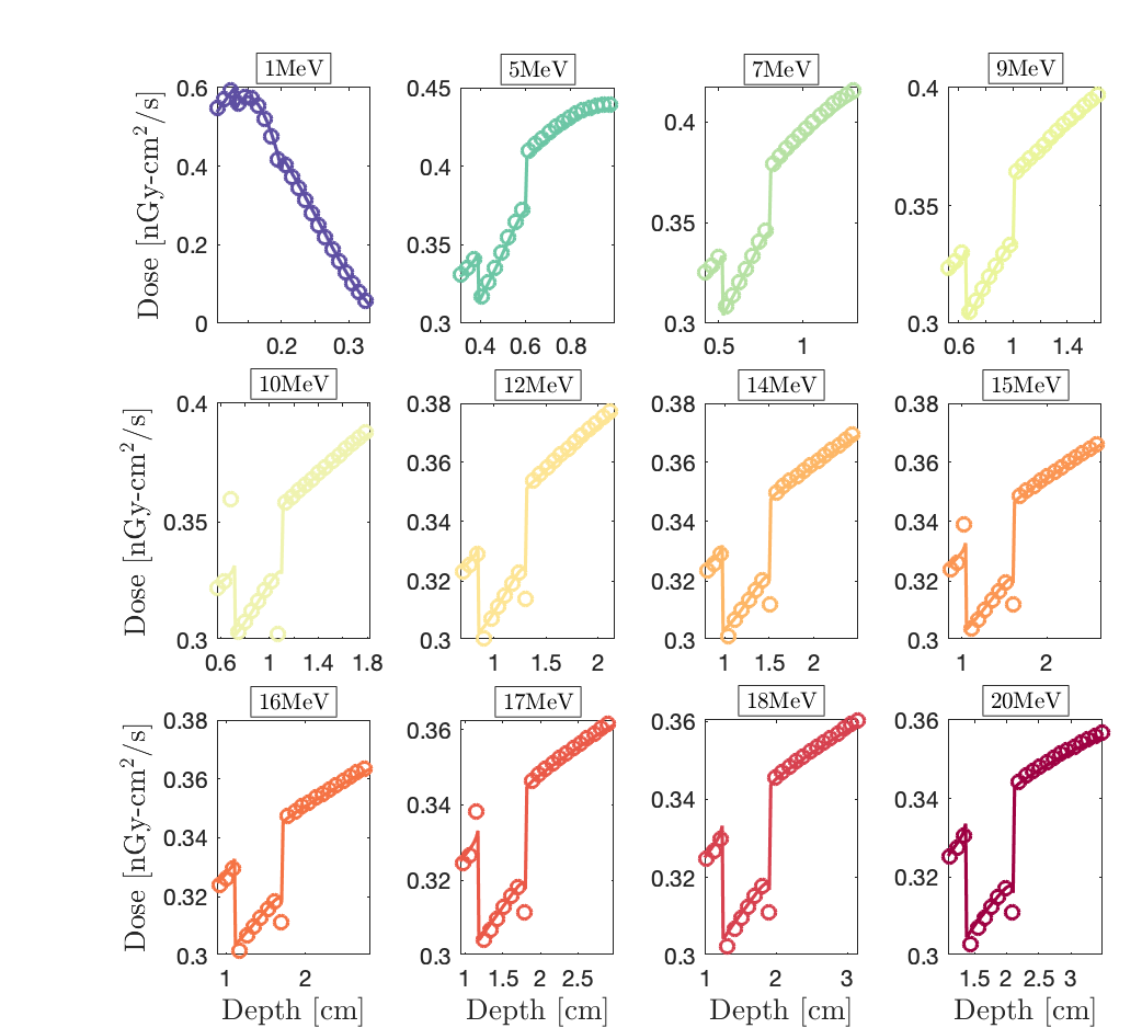
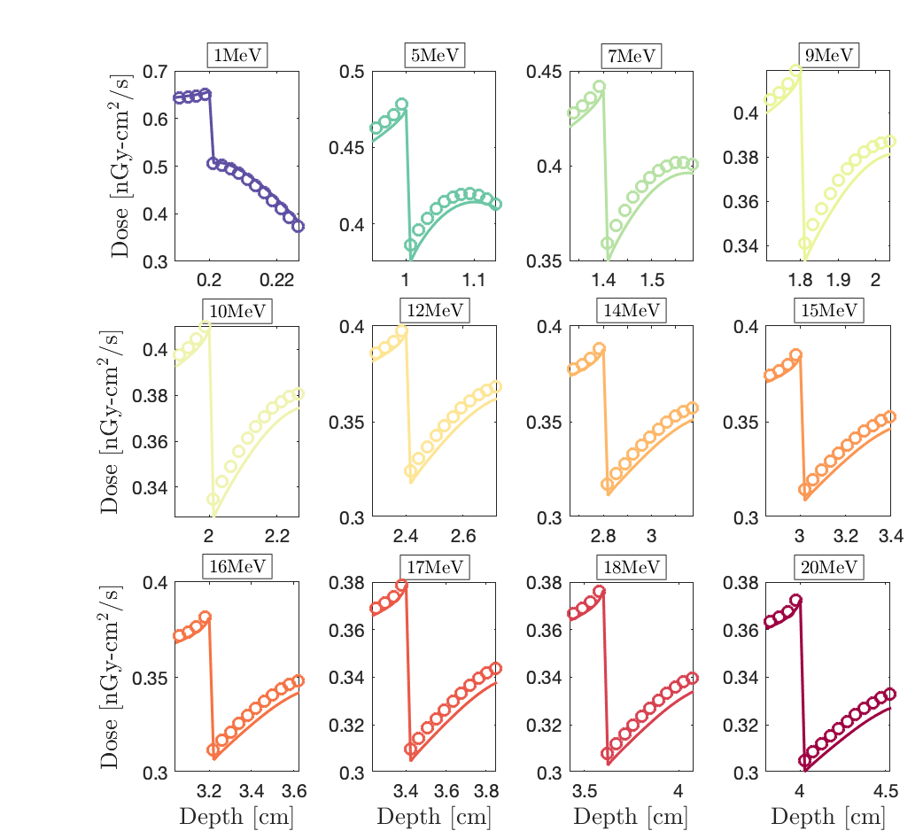
It is noticed that Dragon-5 (solid lines) and Geant-4 (circles) are in perfect agreement in the cancer, the steel and the patient’s breast (Fig.1). They only diverge in aluminum; this time within the Al-buildup and not at the Al-interface (zoom, Fig.2). Do you also think it’s a step optimization problem even if there is no interface discrepancy this time?
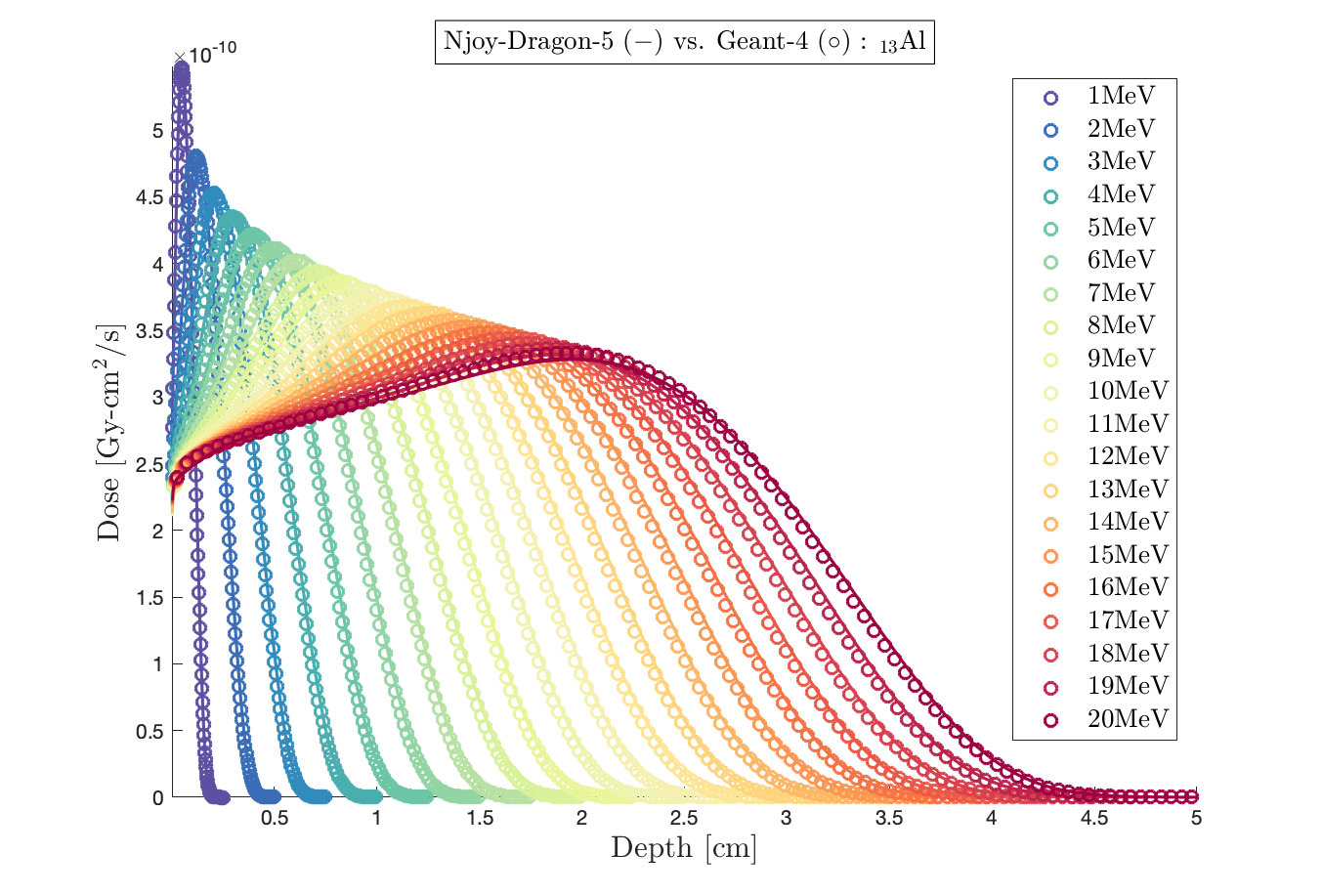
Important note: in a homogeneous aluminum slab, Dragon-5 and Geant-4 give the same dose (please, Fig.3), so it is a not a problem of cross sections’ accuracy.
Thank you.
Hi guatelli
I’m sorry to bother you in this way, but I really need your help. Earlier you suggested me to use parallel geometry or phase space files to simulate the radioactive seed implantation model, and I chose the parallel geometry approach. Since my radioactive seeds are a spiral structure, I can’t define the gps as a cylinder and place it in the source geometry like the brachytherapy example. I need to use /gps/pos/confine to restrict the gps to the source geometry, but it seems that G4 does not support the /gps/pos/confine command to use the physical body defined by parallel geometry. This problem has been bothering me for a long time, so I really appreciate your help.
Dear Jodie, I am not sure. Probably the gps confine method does not work with the parallel geometry? this is something to ask to Makoto Asai asai@slac.stanford.edu
No, I would not touch that StepFunction. You have to define the maximum step in your geometry. Then, for the aluminium, I do not see figure 2. If it is in the build-up region, it could be linked again with the maximum step. Make sure your cut in range is smaller than the bin width.
ok thanks for your reply I will try to ask him, cheers
Once again, thank you @guatelli . Ok, that clarifies more what you mean. I have never forced such a cut in my geometry. Again, just to be sure I understand. Should I follow something as explained in the manual as follows.
In the Tracker region, in order to force the step size not to exceed
one half of the Tracker chamber thickness (chamberWidth), it is enough to put the following code in
B2a::DetectorConstruction::DefineVolumes():
G4double maxStep = 0.5*chamberWidth;
fStepLimit = new G4UserLimits(maxStep);
trackerLV->SetUserLimits(fStepLimit);
and in PhysicsList, the process G4StepLimiter needs to be attached to each particle’s process manager where step limitation in the Tracker region is required:
// Step limitation seen as a process
G4StepLimiter* stepLimiter = new G4StepLimiter();
pmanager->AddDiscreteProcess(StepLimiter);
If a provided GEANT4 physics list is used, as FTFP_BERT in B2 example, then the G4StepLimiterPhysics, which will take care of attaching the G4StepLimiter process to all particles, can be added to the physics list in the main() function:
G4VModularPhysicsList* physicsList = new FTFP_BERT;
physicsList->RegisterPhysics(new G4StepLimiterPhysics());
runManager->SetUserInitialization(physicsList);
@guatelli, once you confirm it, I’ll try that. However, if I understand correctly, we are forcing the particle to have a given behavior at the interface. Is there a more physical method that would correct the situation more naturally (like the step in the G4UrbanMscModel)?
And, here, I’m reposting Fig.2 for the error in the aluminum buildup. The interface is between cancerous tissue and aluminum. I think you keep the same opinion: the error should be corrected in the same way.
Solid lines: Dragon-5 Boltzmann-Fokker-Planck solver for nuclear reactor design and safety analysis.
Circles: Geant-4 with G4EmLivermore physics list.
Please note that using the G4EmStandard library fixes the behaviour perfectly in aluminum, but will show a problem in cancer.
yes, this is the method I suggest (Ahmed, I am on holiday so I am on and off from my e-mails).
Cheers
Susanna