Replicavol phi placements

_Geant4 Version:_4.10.07.p02
Operating System: Linux Fedora 39
_Compiler/Version:_13.2.1 20231205
_CMake Version:_3.27.7


replicated_polar.txt (1.7 KB)
examplePar03.txt (6.3 KB)

It looks to me like there is something wrong with the construction of a replicavol where the total phi angle is less than 360 deg. I think the attached gdml file replicavol_polar.txt (it is a gdml file) should display like the screenshot replicavol_polar_FreeCAD.png, but instead it displays (in geant) as in replicavol_polar_geant.png. Note that in geant the mother volume is not rotated by width/2 so that it completely encloses the daughter tubes; instead it starts at phi=0 in the x direction, where as the replicated tubes start at phi = - 20/2 degrees.

A geometry that has the tubes/sections covering 360 degrees looks correct and it shows the individual tubes starting at phi=-36/2 degrees as expected based on the documentation. GThe fact that the containing mother volume does not start correctly at -36/2 does not matter since the mother tube covers 360 degrees. The attached pictures examplePar03.png and the attached file examplepar03.txt (a gdml file) are from examples/extended/parameterisations/Par03/. I modified the example to export the geometry as a gdml file, but the display with the original version looks the same.


As further tests I tried modifying the starting angle of the Mother tube and added blue color to the slices and red color (with transparency) to the mother voume. It seems the slices rotations are not affected by the mother starting phi. Contrary to to what the documentation says about the slices:

“They have phi of offset+n*width to offset+(n+1)*width where `n=0…nReplicas-1”
Which should place the first slice at phi=0 (offset = 0), the first slice seems to be placed at 10 degrees (=width/2).

Maybe it’s a vis issue. Can you try with RayTracer?

Thanks John for the suggestion.

I don’t think it’s a visualization issue. The attached screenshot shows visualization with style=cloud, which places points at the surfaces, and the surfaces appear at the same place as in the OGL visualizer. I believe something is wrong in the construction of the replica. Both the mother volume of the replica and the replicated sections are tubs with a starting angle of 0 degrees and the offset angle is also 0 degrees, yet the mother volume tube section starts at phi=0, while the slices start at phi=10 degrees.

Hi Munther

The position of a volume, even if drawn as a cloud, is determined by some vis code. I still suspect a vis issue. Please try changing G4PhysicalVolumeModel.cc:382 to

	  rotation.rotateZ (-(offset+n*width));

Let me know if this fixes it. It may be a misunderstanding on my part of the definition of the slice (and a bug of 25 years standing). I would need to double check with its definition in the code that defines replicas - no easy task.

The definitive test is RayTracer.

John

Hi John,

The geometry is defined in a gdml file (attached in my first message as replicated_polar.txt - this web interface does not allow the upload of files with extension .gdml, hence the extension .txt). I display the file using the example for reading gdml files that is supplied with geant: example G01.

I tried exporting a ray trace via /vis/rayTracer/trace filename, but I am getting a seg fault. Let me double check that I have support for the ray tracer in my build first and then I’ll try doing the modification you suggested above.

Munther

Unofrtunaltely RayTracer seems not to work on my system. I located the line you wanted me to change (in my version of geant4.10.07-p02) the line number is 352. I am trying to recompile geant, but getting all sorts of problems. The code in that must have become incompatible with the very recent verion of gcc that I have. It is going to take me a while to recompile… not my day!

Hi Munther

RayTracer is always available. Just “/vis/open RayTracer” and use /vis/viewer commands. Maybe first get a good viewing angle with OGL. It produces a jpg file. If you built with X11, RayTracerX should also be available.

I hadn’t noticed you had included a gdml file. I will try it in the morning.

John

I was finally able to recompile geant (again 10.07-p02) and the above change “fixes” it, in the sense it gives a replica inside its mother volume as expected.

Now the wedges start phi=0, as “expected”. The reason for the quotation marks around “expected” is that the most recent documentation states

" * Phi axis (cylindrical polar) (kPhi)The replications are phi sections or wedges, and of cons/tubs form.

They have phi of offset+n*width to offset+(n+1)*width where n=0..nReplicas-1

The coordinate system of the replicas is at the centre of each replica for the Cartesian axis. For the radial case, the coordinate system is unchanged from the mother. For the phi axis, the new coordinate system is rotated such that the X axis bisects the angle made by each wedge, and Z remains parallel to the mother’s Z axis."

While the equation listed above is in accord now with the changed code, the statement that “the new coordinate system is rotated such that X axis bisects the angle made by each wedge” is not clear to me to be true.

Another posible concern with the fix (which I do hope will be put in the next release) is that some previous constructions might now look different. For example, for wedges that were distributed along 360 degrees (such as the one I gave as examplePar03.png above), the fix gives a setup that looks almost the same:

except now the wedges are rotated by width/2 compared to the previous construction (as of course expected). If anyone was doing any scoring/hits based on the previous location of the wedges, they could potentially get different scoring/hits now.

To me the new code should be the correct one, and the documentation should be adjusted accordingly. I assume you’ll communicate the change you suggested to your fellow developers, but if you think a bug report is warranted, please let me know.

FYI, I am a contributor to the FreeCAD GDML workbench, a tool to import gdml files in FreeCAD and export FreeCAD files into gdml. I stumbled upon the issue I reported above while trying to implement the import of a replicavol from gdml into FreeCAD and what I got looked different from what geant was displaying.

Thanks very much for taking the time to look into this!

Munther

Hi Munther

After a quick look at some of my test code this morning, here are some thoughts.

This is what I wrote many years ago:

    G4double divided_tube_dPhi = tube_dPhi / 6.;
    G4Tubs* divided_tube = new G4Tubs
      ("divided_tube",
       20*cm,50*cm,30*cm,-divided_tube_dPhi/2.,divided_tube_dPhi);
    G4LogicalVolume * divided_tube_log
      = new G4LogicalVolume(divided_tube,Ar,"divided_tube_L",0,0,0);
    divided_tube_log->SetVisAttributes(grey);
    new G4PVReplica("divided_tube_phys",divided_tube_log,tube_log,
		    kPhi,6,divided_tube_dPhi);

It looks like I interpreted the instructions as meaning I had to construct a solid (G4Tubs) that had its x-axis bisecting the angular range, so it starts at -divided_tube_dPhi/2 and has a range of divided_tube_dPhi.

How does GDML do it?

The test is RayTracer. I will give it a go.

John

OK. More…

Not easy to see with RayTracer. Perhaps place something inside so we can see it?

But, as far as I can see, it looks OK.

However, I can show that your replica has start_phi=0 and dphi=range. That’s with /vis/set/touchable and /vis/touchable/draw and /vis/touchable/localAxes. The x-axis should (it says) bisect the slice, but as you see, it is along one of the sides.

My problem is: how can they both be OK? Maybe there is some compensation in G4Replica. Regarding vis, I could pick up the start and range and adjust accordingly, but I need to understand this.

The problem remains: is it still OK as far as tracking is concerned?

John

Hi John,

I am in Seattle (GMT -8). So delays in my repsonses are probably due to time difference between us.

How does GDML do it?

I checked the C++ code that reads the GDML document and creates the replica. It does not insert anything new on its own; it just reads the parameters in the gdml file and calls G4ReflectionFactor.Divide(…)

From my tests, and looking at the GDML code, it looks like one can adjust the start_phi of the mother volume and the start_phi of the slice separately and independantly of each other. So in principle one can always ensure that the replicas fit inside their mother volume by adjusting the start_phi of either the mother or the slice. The point of possible confusion is that, with the existing C++ code in G4PhysicalVolumeModel.cc (which adds a 0.5
*width to the rotation of each slice), one has to use start_phi_mother = 0, and start_phi_slice = -width/2, as you do in your above sample code, in order to get the slices to fit completely inside the mother. To me this is unnatural and confusing and I would have prefered a construction in which the 0.5*width is removed from rotation.rotateZ so that start_phi_mother = start_phi_slice leads to the slices being inside the mother.

I am assuming the developers (you included!) would not like to change the code, so as to preserve previous users’ code working the way it was. I can live with that, but then the documentation does have to change to state that wedges:
“They have phi of offset+(n+0.5) *width to offset+(n+1+0.5)*width where `n=0…nReplicas-1”
rather than the current version missing the 0.5*width.

I finally go the RayTracer to work, but I am not sure it allows you to see inside transparent voumes. But it shows an outline that is the same as what OpenGL shows.

The gdml file I use has transparency in the color of both the mother volume and the slices, so I can see through them. I suppose you can use /vis/geometry/set/colour to add transparency so you can see inside the slices.

Please let me know which way you decide to go, so I can adjust my GDML->CAD software to reflect what geant does.

Thanks!

Munther

Hi Munther

I think we’ve got to the bottom of this. The good thing is that none of this affects tracking/physics - it’s purely a vis thing.

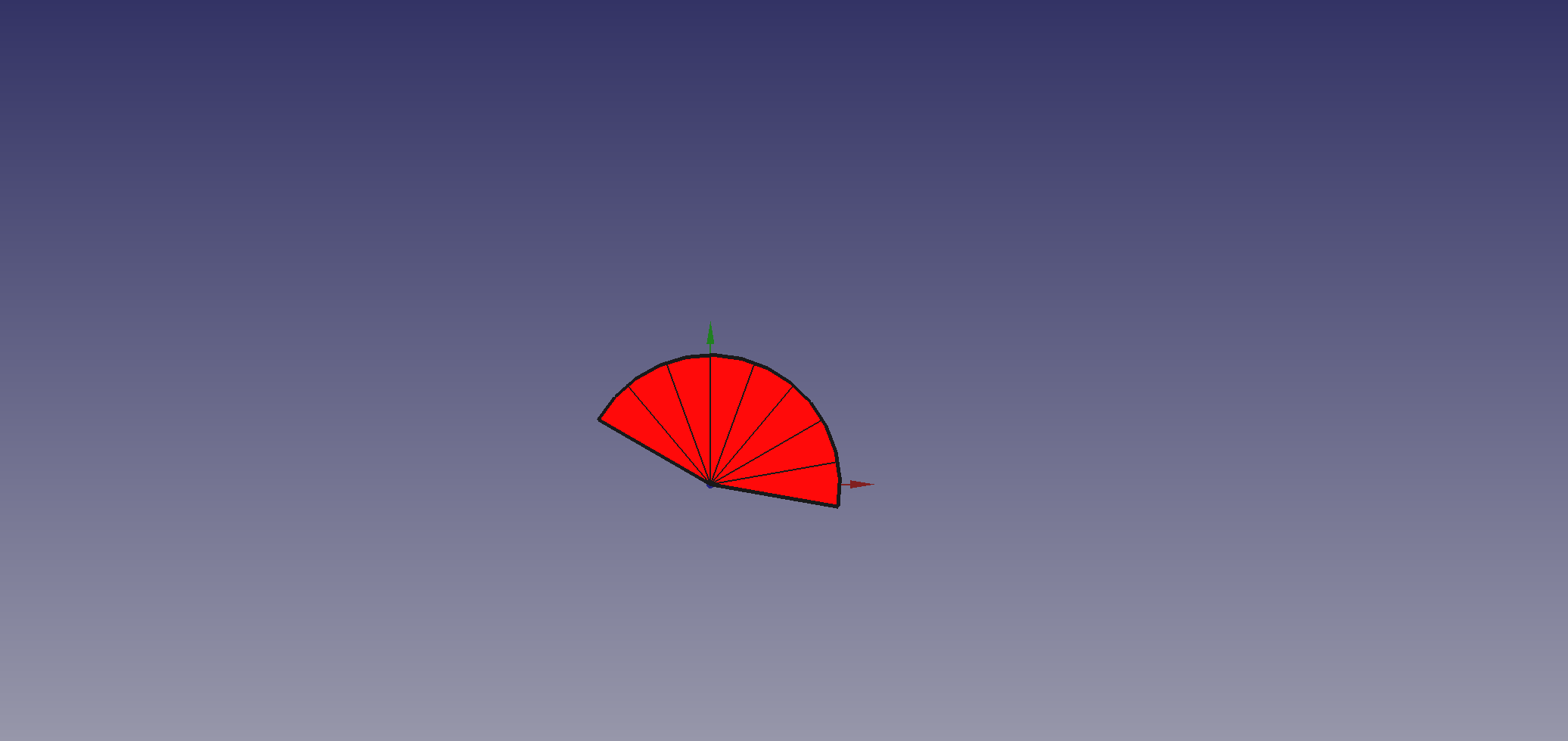
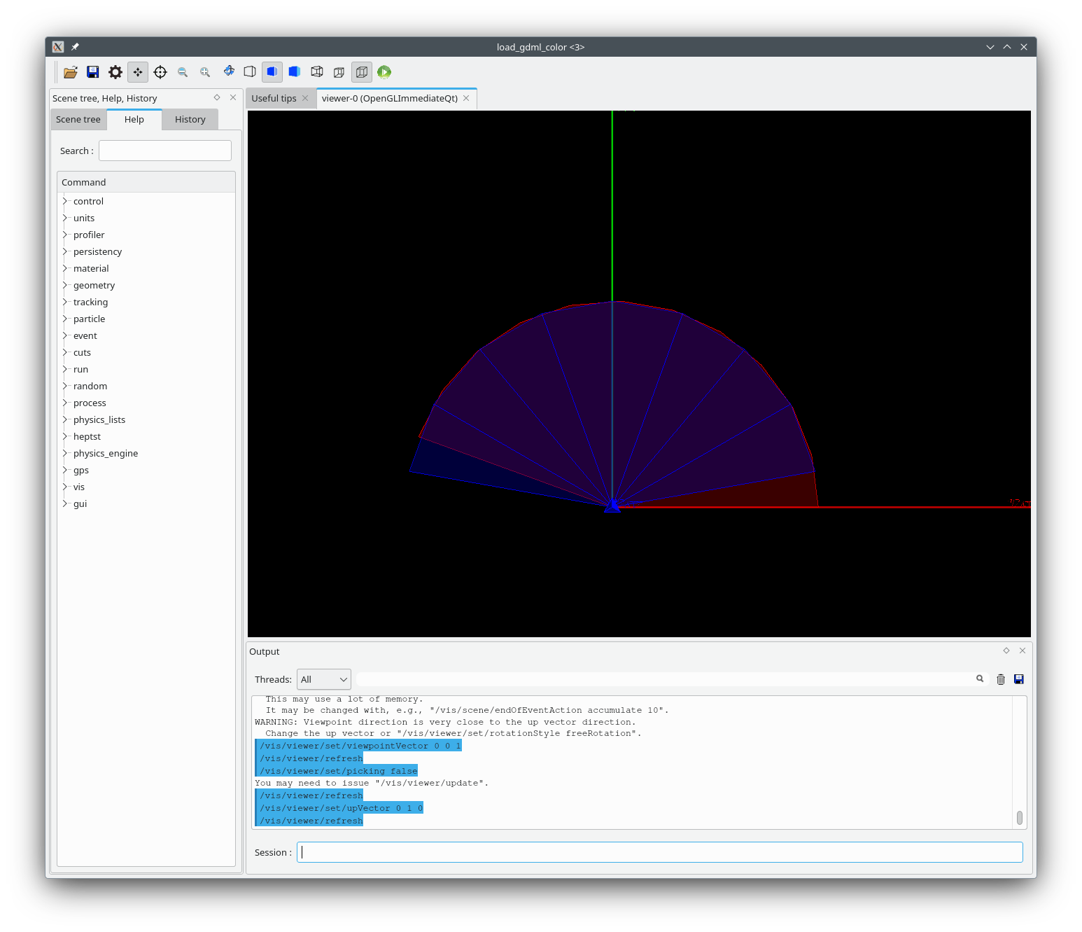
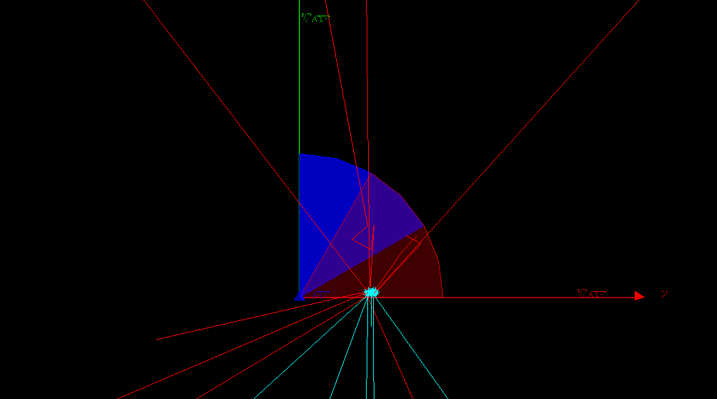
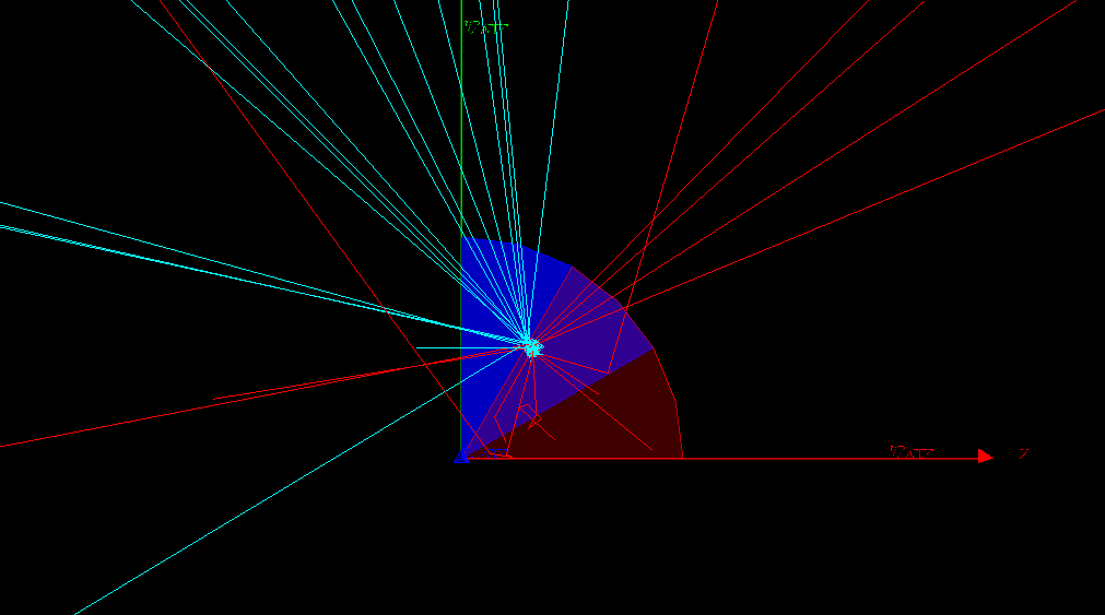
The existing code assumes the solid for visualising the phi section should have a start_phi of offset-0.5*width and a d_phi of width. The advantage is that the x-axis bi-sects the slice and correctly represents the local coordinate system adopted by replica navigation, which is used to place daughters, as described in the documentation:

For the phi axis, the new coordinate system is rotated such that the X axis bisects the angle made by each wedge…

The documentation is vague:

The solid associated via the replicas’ logical volume should have the dimensions of the first volume created and must be of the correct symmetry/type, in order to assist in good visualisation.

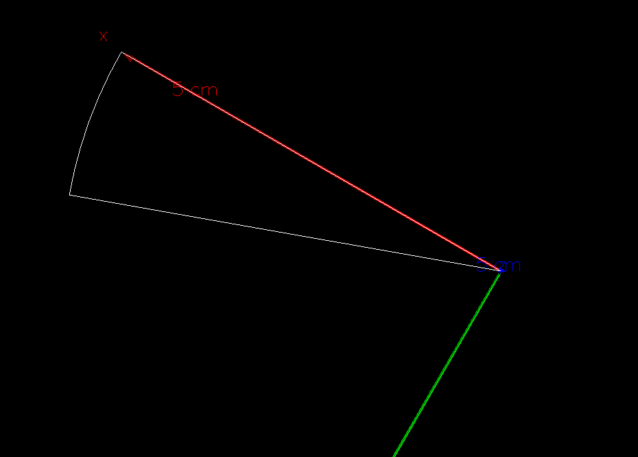
The only time anyone would notice any local axes discrepancy is with /vis/touchable/localAxes.

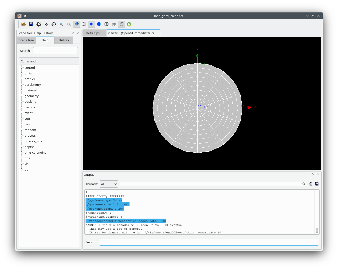
Looking at some test code written by the designers in 1995 (!) its looks like they adopt your convention:

  G4Sphere* fSphere = new G4Sphere("Test Sphere",0.,80.,0*deg,360*deg,0*deg,360*
deg);
  G4LogicalVolume *pMotherVol2P= new G4LogicalVolume(fSphere, 0, "lmoth2P", 0, 0, 0);
    new G4PVPlacement(0,G4ThreeVector(),"pmoth2",pMotherVol2P,hall_phys2,false,0);
...
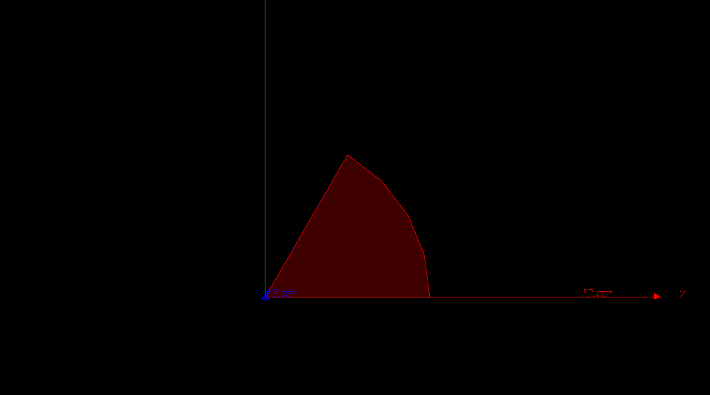
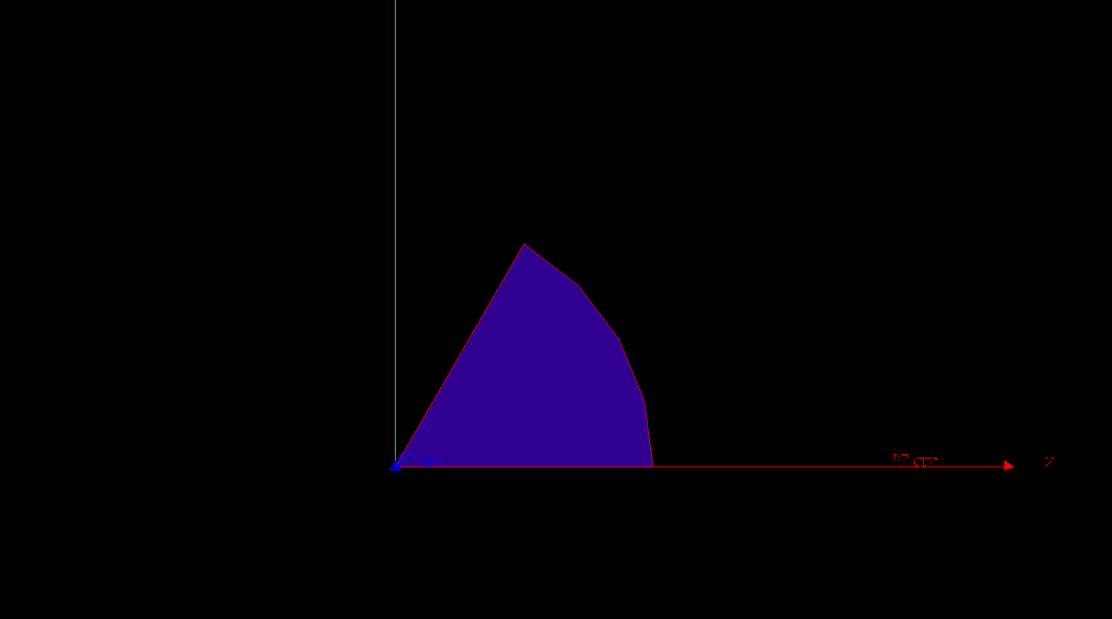
  G4Sphere* fSphereP = new G4Sphere("Sliced Sphere Phi",0.,80.,0*deg,90*deg,0*deg,360*deg);
  G4LogicalVolume* phiSphereLog= new G4LogicalVolume(fSphereP, 0, "PhiSlice", 0, 0, 0);
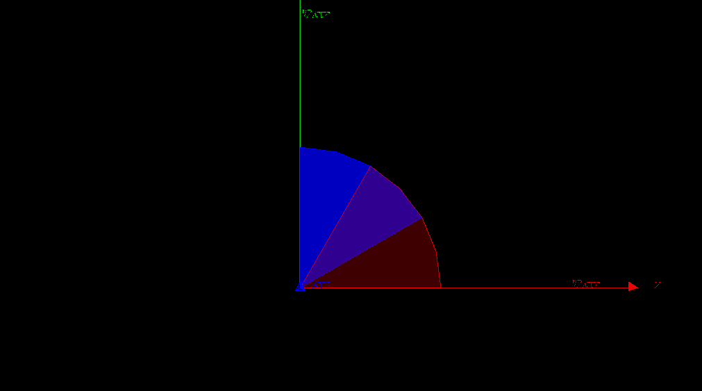
  G4PVReplica phiRep("TestPhi",phiSphereLog,pMotherVol2P,kPhi,4,pi*0.5);

but it’s difficult to tell because it’s a full circle.

I’m going to consult. No-one else has commented in 25 years. Has anyone noticed? How many users would get a surprise if we changed? I’ll get back.

John

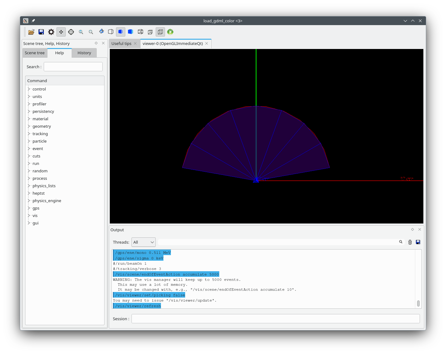
P.S. If we keep the existing vis code:

I think we should, in any case, improve the documentation.

…to assist in good visualisation. In particular, to make the local axes of the visualisable phi section correspond to the above, it should have a start_phi of offset-0.5*width and a d_phi of width.

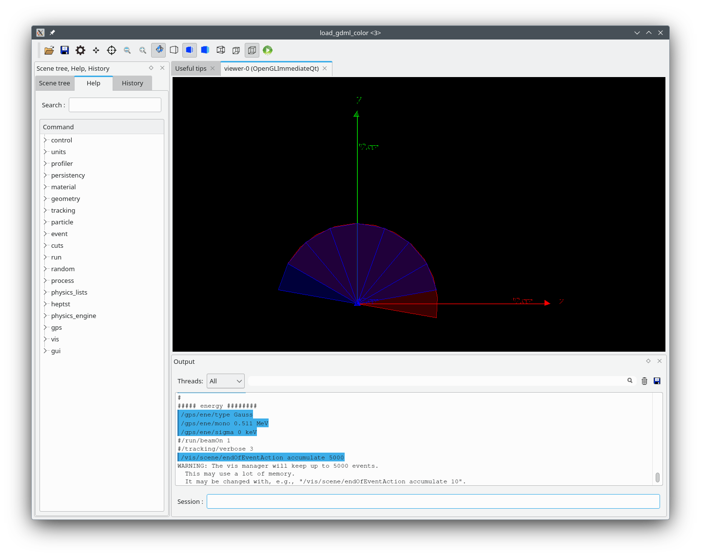
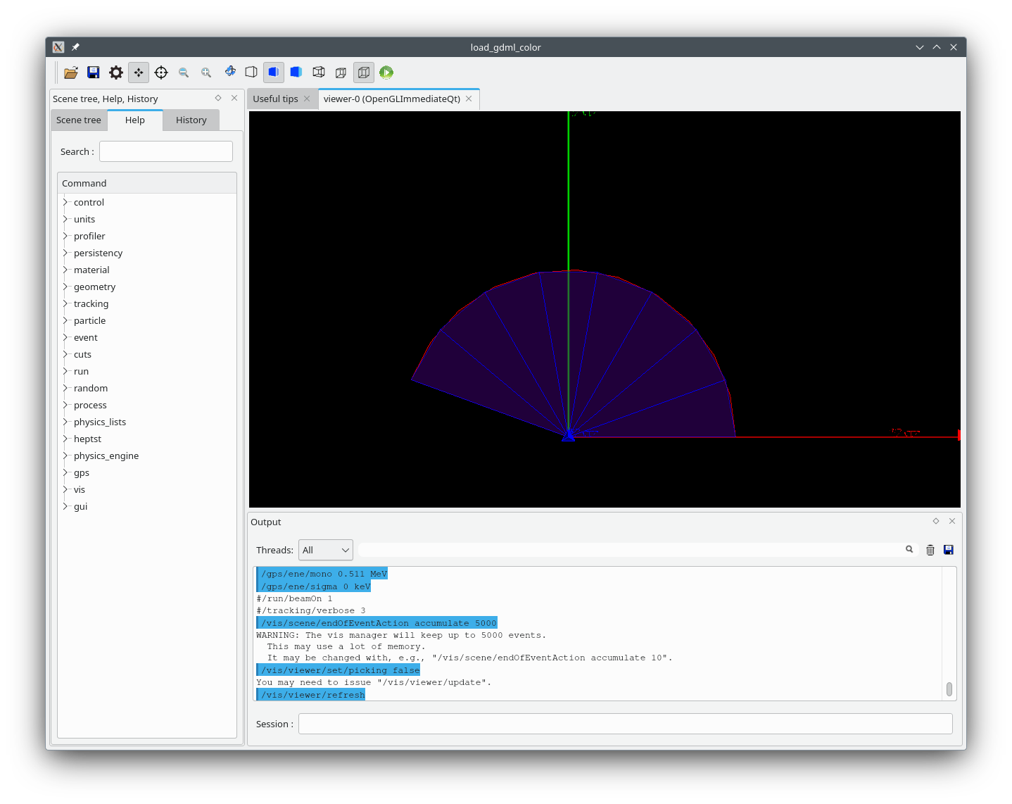
Or for your preferred convention:

…to assist in good visualisation. In particular, the phi section should have a start_phi of offset and a d_phi of width.

Hi John,

I present here five figures; the main purpose was to motivate why the current code and documentation looked (and still does) off to me. However, I found, to my surprise, that the issue seems to be a visualization and not a tracking issue. The tests were:

  1. Place a single tube with start phi = 0 and deltaphi=60 deg. The gdml file and the screen shot are (note that the red line is the x-axis and the green line the y axis):
    replicated_polar-test1.gdml.txt (1.4 KB)

  2. “Manually” place inside the above (logical) volume another tube with the same dimension and starting point. To try and distinguish the mother from the daughter, the mother is coloured with a transparent red and the dughter with a solid blue.
    replicated_polar-test2.gdml.txt (1.6 KB)


    The position of the daughter is what one would expect.

  3. Now instead of manually placing the daughter tube inside the mother, insert a replicavol in the mother, with number of replicas = 1. Again, start phi is still 0, as in the above.
    replicated_polar-test3.gdml.txt (1.8 KB)


    To me the appearance of the replicated volume outside its mother looks odd. Now we know that it is because of the extra 0.5*width in G4PhysicalModel.cc.

  4. To test whether this is only a visualization issue, or whether the daughter is placed (partially) outside its mother, I fired a beam of 2 MeV electrons at the mother. First in the +y direction (up).


    Note that the beam seems to interact with the mother (the red tube). However, the mother tube is made of AIR and the beam should have penetrated quite a bit more into the mother.

  5. To double check, I fired the beam in the +x direction m (to the right) as in the figure:


    To my surprise (but you’ve been saying all along it is a visualization issue), the beam does not interact with the “blue” tube, but with the Aluminum tube inside the mother volume.

So it looks like the replicavol is constructed correctly inside its mother, but displayed wrongly if the start phi is not adjusted by width/2.

Hi Munther

Yes, it is indeed purely a vis issue. In fact, I think replica navigation does not use the solid at all - it just uses the mother’s parameters, divided as requested. And it defines a local coordinate system that may be used to place daughters inside the replica. In the case of a phi-section, the x-axis bi-sects the angles of the phi faces, so it makes sense to define the solid this way, even though it is only used for visualisation. In fact, if you replaced replicas with placements, and wished to use the same code to place daughters within, that it how you would have to define the solid.

I am waiting for comments from geometry colleagues, but I think we will probably keep the current convention.

I’m glad we have got to the bottom of this. I wonder if other GDML providers have faced this issue, but at least FreeCAD will be conformant, thanks to your diligence.

John

Hi Munther

I can confirm it’s our intention to keep the current convention for adding a solid for visualisation. I will improve the documentation and make a specific recommendation in the case of a phi-section.

Thanks again for your diligence and for contributing to the continuing cooperation between Geant4 and FreeCAD.

John

Hi John,

Thanks for taking the time to look into this. Hopefully the documentation will reflect how the slices are drawn. To me it is weird that a solid is drawn in one place, but particles interact with it in a different place. To me the onus should be on geant to draw solids to reflect where they are in the tracking system, rather than rely on the user to specify the correct starting phi to make the visualized solid match the tracked solid. However, I quite understand that, given the limited resources available for the geant developers, a change to the code cannot/should not be undertaken.

Thanks again, I really appreciate your attention to this.

Munther

This topic was automatically closed 7 days after the last reply. New replies are no longer allowed.