Union of union of Boolean solids

Hi
I have several problems with constructing a union of solids…
I am generating a lens using union of union of annular concentric truncated spheres.

  1. Union of union does not work i.e., when I try to visualize the object it fails to show up.
  2. I can only make union of two solids and then a union of another solid and that resulting boolean solid but not union of two boolean solids
  3. So stick with my original plan of only doing a pair of several unions. Now I need to translate all these multiple solids over several thousands of km, and when I do that the lens get completely distorted and does not look like a lens anymore.
  4. I could instead first translate each solid of the boolean pair first and then do a union. But then that first solid is also now included in my geometry which I do not want. And not sure if this will still solve that problem
    Any suggestions are welcome
    Thanks

Have you looked at G4MultiUnion? It was introduced with G4 10.01, and allows you to provide a whole list of solids, each with an associated transformation (relative to the first solid on the list), and it unions them together in one shot.

I haven’t used it to make anything, but I have used it to create the “intermediate” collection of things for a big subtraction.

I think that the problems are not related to the usage of boolean union, but to the size of the model. “Several thousands of km” is a lot, the size of lenses in this case is negligible in comparison with the distance to the source of particles. Anyway I would suggest to try the following:

  1. Do not move the lenses, but the gun of particles. Start with smaller distance, and then step by step increase it, to figure out at what distance you will start to see the problems.
  2. Surround the set of lenses by bounding box. In this case the navigator will first move particles to the border of the box, and only after that calculate intersection with the surface of lenses.
  3. Try to use G4Ellipsoid instead of G4Sphere. G4Ellipsoid may be cut by a plane, that could be more convenient than a cut in theta angle. In addition the code of G4Ellipsoid has been recently revised and I don’t exclude that it is more robust and performant than G4Sphere.

Hi Evc
Even with no large order of geometry i.e., just a localized lens - union of union does not seem to show up in the 3D viewer.
its possible that the viewers have an issue. I tried two different viewers but they both do not show the geometry.
However, thank you for your other suggestion when I do work with km ranges. I will follow it up. I did build a G4ellipsoid lens but have not tried at long range displacement.

Sometimes the vis system has problems with boolean solids. Were there any warning messages?

Note: this does not necessarily affect tracking - it is purely a visualisation issue. It is tricky, sometimes, to represent boolean solids in a form suitable for visualisation. You could try visualising with the Ray Tracer or (from Geant4 10.6) with /vis/viewer/set/style cloud, which use different ways of representing solids for visualisation.

Hi Allison
I doubt that it’s Visualization because no data itself is being generated. I played a lot and looks like after re-reading the manual it clearly says for creating a boolean solid the main requirements is availability of two solids or a solid and a Boolean solid. There’s also something about shared volumes but I don’t quite get it from the manual.
But as soon as I try to merge two Booleans - if they overlap - union of Boolean does not work. If they don’t overlap or are just barely touching then I am able to create a third Boolean of Union of pairs of Boolean.

Hi Rajan,
Could you share your code where the lens is defined. It will be easier to understand the source of the problem.

Yes sure!
The code is translated into a GAMOS script but its fairly easy to figure out. There are two of those, one that did not work i.e generated no solid data (and I have included error messages from GAMOS output) and the other that did work …

The one that DID NOT work. The error message is provided at the end of the script below.
{beginning of script 1
// BUILD GEOMETRY

:VOLU world BOX 10.*m 10.*m 10.*m G4_AIR
:VIS world OFF
:Colour world 0. 0. 1.

:ROTM RM0 0. 0. 0.

:VOLU sph1 SPHERE 195.*cm 200.*cm 0.*deg 360.*deg 0.deg 3.0deg G4_Pyrex_Glass

:VOLU sph2 SPHERE 195.*cm 200.*cm 0.deg 360.deg 2.9deg 6.0deg G4_Pyrex_Glass

:VOLU sph4 SPHERE 195.*cm 200.*cm 0.deg 360.deg 5.9deg 9.0deg G4_Pyrex_Glass

:VOLU sph5 SPHERE 195.*cm 200.*cm 0.deg 360.deg 8.9deg 12.0deg G4_Pyrex_Glass

:VOLU sph6 SPHERE 195.*cm 200.*cm 0.deg 360.deg 11.9deg 15.0deg G4_Pyrex_Glass

:VOLU sph7 SPHERE 195.*cm 200.*cm 0.deg 360.deg 14.9deg 18.0deg G4_Pyrex_Glass

:SOLID spc UNION sph1 sph2 RM0 0.*mm 0.*mm 0.*mm
:VOLU spc spc G4_Pyrex_Glass

:SOLID spc2 UNION sph4 sph5 RM0 0.*mm 0.*mm 0.*mm
:VOLU spc2 spc2 G4_Pyrex_Glass

:SOLID spc4 UNION spc spc2 RM0 0.0mm 0.0mm 0.0mm
:VOLU spc4 spc4 G4_Pyrex_Glass
:PLACE spc4 1 world RM0 0.0
cm 0.0cm 0.0mm

//make sph1 as the final GmGenerDistPositionInG4Volumes in .in file. If you use any other such as spc4 it does not work strangely…
:VOLU sph3 SPHERE 0. 20.*mm 0.*deg 360.*deg 0.deg 2.0deg G4_Pyrex_Glass
:PLACE sph3 1 spc4 RM0 0. 0. 0.
:VIS sph3 OFF
end of script 1}

Error messages:
-------- WWWW ------- G4Exception-START -------- WWWW -------
*** G4Exception : Two world volumes found, second will be taken
issued by : G4tgrVolumeMgr::GetTopVolume()
Both volumes are at the top of a hierarchy: spc & world
*** This is just a warning message. ***
-------- WWWW -------- G4Exception-END --------- WWWW -------

AND

G4Scene::AddWorldIfEmpty: The scene was empty of run-duration models.
“world” has been added.

AND

===========================================
Output VRML 2.0 file: g4_00.wrl
Maximum number of files in the destination directory: 100
(Customizable with the environment variable: G4VRMLFILE_MAX_FILE_NUM)

ERROR: G4VSceneHandler::RequestPrimitives
Polyhedron not available for spc4
Touchable path: world 0 spc4 1
This means it cannot be visualized on most systems (try RayTracer).

  1. The solid may not have implemented the CreatePolyhedron method.
  2. For Boolean solids, the BooleanProcessor, which attempts to create
    the resultant polyhedron, may have failed.
    *** VRML 2.0 File g4_00.wrl is generated.


This changed solid geometry DOES WORK!
{beginning of script2…
Here is the geometry file

// BUILD GEOMETRY

:VOLU world BOX 10.*m 10.*m 10.*m G4_AIR

:ROTM RM0 0. 0. 0.
:VIS world OFF
:Colour world 0. 0. 1.

:VOLU sph1 SPHERE 195.*cm 200.*cm 0.*deg 360.*deg 0.deg 3.0deg G4_Pyrex_Glass

:VOLU sph2 SPHERE 195.*cm 200.*cm 0.*deg 360.*deg 3.deg 3.0deg G4_Pyrex_Glass
#Even if I make the above start theta to be 3.1 deg instead of 3 for sph2 it works!!

:VOLU sph4 SPHERE 195.*cm 200.*cm 0.*deg 360.*deg 6.deg 3.0deg G4_Pyrex_Glass

:VOLU sph5 SPHERE 195.*cm 200.*cm 0.*deg 360.*deg 9.deg 3.0deg G4_Pyrex_Glass

:VOLU spc UNION sph1 sph2 RM0 0.*mm 0.*mm 0.*mm G4_Pyrex_Glass

:VOLU spc2 UNION sph4 sph5 RM0 0.*mm 0.*mm 0.*mm G4_Pyrex_Glass

:VOLU spc4 UNION spc2 spc RM0 0.0mm 0.0mm 0.0*mm G4_Pyrex_Glass

:PLACE spc4 1 world RM0 0.0cm 0.0cm 0.0*mm

:VIS spc4 ON

//make sph1 as the final GmGenerDistPositionInG4Volumes in .in file. If you use any other such as spc4 it does not work strangely…
:VOLU sph3 SPHERE 0. 20.*mm 0.*deg 360.*deg 0.deg 2.0deg G4_Pyrex_Glass
:PLACE sph3 1 world RM0 0. 0. 0.
:VIS sph3 OFF

end of script2}

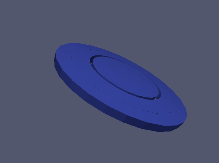
I am attaching a .png of an spc4 lens created by this second script except that (surprisingly!) I had NO overlap between the two Boolean solids spc and spc2 (unlike in the above script where they touch each other on one face). And yet it generated a single Boolean from both.

And the following DID NOT work
In this case I am making Boolean from two SG solids OR an SG solid and a Boolean.
i.e. solid sph1+solid sph2 it generated a Boolean spc
spc +solid sph4 it generated a Boolean spc3.
But spc3 + solid sph5 : Did not generate a Boolean solid spc4 if the two had overlap . As soon as I reduced the overlap to zero (changed 8.9 in bold below to 9.0) it DID generate an spc4 Boolean. So I am unable to understand the intricacies of Boolean construction.

// BUILD GEOMETRY

:VOLU world BOX 10.*m 10.*m 10.*m G4_AIR
:ROTM RM0 0. 0. 0.
:VIS world OFF
:Colour world 0. 0. 1.

//:ROTM RM1 0.2 0.0 0.0

:VOLU sph1 SPHERE 195.*cm 200.*cm 0.*deg 360.*deg 0.deg 3.0deg G4_Pyrex_Glass
//:PLACE sph1 1 world RM0 0 0 0

:VOLU sph2 SPHERE 195.*cm 200.*cm 0.deg 360.deg 2.9deg 3.1deg G4_Pyrex_Glass
//:PLACE sph2 1 world RM0 0 0 0

:VOLU sph4 SPHERE 195.*cm 200.*cm 0.deg 360.deg 5.9deg 3.1deg G4_Pyrex_Glass

:VOLU sph5 SPHERE 195.*cm 200.*cm 0.deg 360.deg 8.9deg 3.1deg G4_Pyrex_Glass

:VOLU spc UNION sph1 sph2 RM0 0.*mm 0.*mm 0.*mm G4_Pyrex_Glass
//:PLACE spc 1 world RM0 0 0 0
//:VIS spc OFF

//:VOLU spc2 UNION sph4 sph5 RM0 0.*mm 0.*mm 0.*mm G4_Pyrex_Glass
//:PLACE spc2 1 world RM0 0 0 0
//:VIS spc2 ON

:VOLU spc3 UNION spc sph4 RM0 0.0mm 0.0mm 0.0mm G4_Pyrex_Glass
//:PLACE spc3 1 world RM0 0.0
cm 0.0cm 0.0mm
//:VIS spc3 OFF

//:VOLU spc4 UNION spc2 spc RM0 0.0mm 0.0mm 0.0mm G4_Pyrex_Glass
:VOLU spc4 UNION spc3 sph5 RM0 0.0
mm 0.0mm 0.0mm G4_Pyrex_Glass
:PLACE spc4 1 world RM0 0.0cm 0.0cm 0.0*mm
:VIS spc4 ON

//make sph1 as the final GmGenerDistPositionInG4Volumes in .in file. If you use any other such as spc4 it does not work strangely…
:VOLU sph3 SPHERE 0. 20.*mm 0.*deg 360.*deg 0.deg 2.0deg G4_Pyrex_Glass
:PLACE sph3 1 world RM0 0. 0. 0.
:VIS sph3 OFF

Attached is a figure where spc4 is generated after I changed sph5 start angle from 8.9 to 9.0. Otherwise no solid is generated from the above script and the error is similar to previous posted result i.e., no polyhedra is created.
Thanks

Hi Rajan,

You did not tell us that you are using GAMOS and most of the advices in this topic were relevant to direct usage of Geant4. I do not know GAMOS, but it seems that in your script there is a misuse of solids and volumes.

In Geant4 there are three main types of geometry objects: solids, logical volumes and physical volumes.

Solid is just a shape: box, tube, sphere, etc. Logical volumes include also information on material. Physical volume has also information on its position in the mother volume.

It looks that GAMOS do not explicitly distinguish logical and physical volumes, but it does not big matter, it does it implicitly.

Now let me make a couple of advices, that, I hope, will help to resolve the issue.

  1. Create solids and volumes separately, I mean, first create solid, then volume.
  2. Do not use the same name for solid and volume. For example, use prefix s_ for names of solids and prefix v_ for names of volumes.

If to follow the above advices then the code in your script will look like the following:

:SOLID s_world BOX 10.*m 10.*m 10.*m
:VOLU v_world s_world G4_AIR
:VIS v_world OFF
:COLOUR v_world 0. 0. 1.

:ROTM RM0 0. 0. 0.

:SOLID s_sph1 SPHERE 195.*cm 200.*cm 0.*deg 360.*deg 0. *deg 3. * deg
:SOLID s_sph2 SPHERE 195.*cm 200.*cm 0.*deg 360.*deg 3. *deg 3. * deg

:SOLID s_sph4 SPHERE 195.*cm 200.*cm 0.*deg 360.*deg 6. *deg 3. * deg
:SOLID s_sph5 SPHERE 195.*cm 200.*cm 0.*deg 360.*deg 9. *deg 3. * deg

:SOLID s_spc UNION s_sph1 s_sph2 RM0 0. *mm 0. *mm 0. *mm
:SOLID s_spc2 UNION s_sph4 s_sph5 RM0 0. *mm 0. *mm 0. *mm
:SOLID s_spc4 UNION s_spc2 s_spc RM0 0. *mm 0. * mm 0. *mm

:VOLU v_spc4 s_spc4 G4_Pyrex_Glass
:PLACE v_spc4 1 v_world RM0 0. *cm 0. * cm 0. *cm

The problem should disappear.

Cheers,
Evgueni

Thanks Evgueni
I will follow your advice and report back…

Unless I made a mistake, the suggestion by Evgueni DID NOT work out and getting exactly same error about
Polyhedron not available for s_spc4
Touchable path: v_world 0 v_spc4 1

// BUILD GEOMETRY

:SOLID s_world BOX 10.*m 10.*m 10.*m
:VOLU v_world s_world G4_AIR
:ROTM RM0 0. 0. 0.
:VIS v_world OFF
:Colour v_world 0. 0. 1.

//:ROTM RM1 0.2 0.0 0.0

:SOLID s_sph1 SPHERE 195.*cm 200.*cm 0.*deg 360.*deg 0.deg 3.0deg
//:PLACE sph1 1 world RM0 0 0 0

:SOLID s_sph2 SPHERE 195.*cm 200.*cm 0.deg 360.deg 2.9deg 3.1deg
//:PLACE sph2 1 world RM0 0 0 0

:SOLID s_sph4 SPHERE 195.*cm 200.*cm 0.deg 360.deg 5.9deg 3.1deg

:SOLID s_sph5 SPHERE 195.*cm 200.*cm 0.deg 360.deg 8.0deg 3.1deg

:SOLID s_spc UNION s_sph1 s_sph2 RM0 0.*mm 0.*mm 0.*mm
//:PLACE spc 1 world RM0 0 0 0
//:VIS spc OFF

//:VOLU spc2 UNION sph4 sph5 RM0 0.*mm 0.*mm 0.*mm G4_Pyrex_Glass
//:PLACE spc2 1 world RM0 0 0 0
//:VIS spc2 ON

:SOLID s_spc3 UNION s_spc s_sph4 RM0 0.0mm 0.0mm 0.0mm
//:PLACE spc3 1 world RM0 0.0
cm 0.0cm 0.0mm
//:VIS spc3 OFF

//:VOLU spc4 UNION spc2 spc RM0 0.0mm 0.0mm 0.0mm G4_Pyrex_Glass
:SOLID s_spc4 UNION s_spc3 s_sph5 RM0 0.0
mm 0.0mm 0.0mm
:VOLU v_spc4 s_spc4 G4_Pyrex_Glass
:PLACE v_spc4 1 v_world RM0 0.0cm 0.0cm 0.0*mm
:VIS v_spc4 ON

//make sph1 as the final GmGenerDistPositionInG4Volumes in .in file. If you use any other such as spc4 it does not work strangely…
:SOLID s_sph3 SPHERE 0. 20.*mm 0.*deg 360.*deg 0.deg 2.0deg
:VOLU v_sph3 s_sph3 G4_Pyrex_Glass
:PLACE v_sph3 1 v_world RM0 0. 0. 0.
:VIS v_sph3 OFF

Just a single line change and this worked…
Hope someone can explain why is that?

Changed the s_sph5 solid definition from
:SOLID s_sph5 SPHERE 195.cm 200.cm 0.deg 360.deg 8.0deg 3.1deg
to
:SOLID s_sph5 SPHERE 195.cm 200.cm 0.deg 360.deg 9.0deg 3.1deg

Before to render the geometry the default vis system converts the solids to polyhedra. For boolean solids this conversion sometimes fails and system print a message that Poyhedron not available.

However, this does not necessary mean that there is a problem in tracking. This is why John Allison has advised you to try rendering with the Ray Tracer, which is based on the tracking algorithms.

In case if the components of a boolean union do not penetrate each other, there is no need to create the union. Very often users join a set of solids into a boolean union to have a possibility to move them together. This can be done by other means, for example, by using an Assembly. Other possibility is to place all the solids in additional mother volume and apply transformation to it.

Thanks Evc,
I will try the RayTracer. I have not installed it but will do so. I think I understand your’s and John’s logic.
My solids aren’t necessarily overlapping but as you guessed not only I have to move them someplace else, I also have to cut them i.e., create a Boolean, create another repeat but offset and then take their intersection. And then translate and rotate that resulting intersection piece. I should try the Assembly suggestion.