Hi,
I’m trying to simulate the electron cloud generated by x rays in HgCdTe as part of my PHD. While analyzing the angular distribution for the fluorescence X rays, I noticed that :
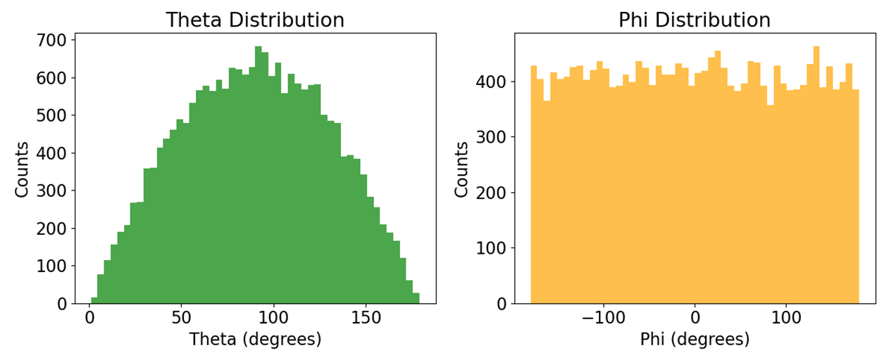
their angular distributions are the same than the one for the primary photoelectric electron distribution.
However, thoses x rays are supposed to be isotropic (at least we can suppose that they are , accoding to https://www.oecd-nea.org/upload/docs/application/pdf/2020-10/penelope-2018__a_code_system_for_monte_carlo_simulation_of_electron_and_photon_transport.pdf). I simulated everything with the Peneloppe model and the fluorescence generation is working well (i can see some fluo x rays inside my logs). This is the code that logs this data (part of it) : ```
// — Pre-calculate kinematics —
const auto momentumDir = track->GetVertexMomentumDirection();
double theta = momentumDir.theta() * 180.0 / M_PI;
double phi = momentumDir.phi() * 180.0 / M_PI;
/*// Correction for negative X momentum (specific legacy logic)
if (track->GetMomentum().x() < 0) {
theta = 360.0 - theta;
}
*/
const auto pos = (post->GetPosition() + pre->GetPosition()) / 2.0;
const auto corrected_pos = pos - this->fOriginPrimary; // Now guaranteed to be initialized
if (!fanalysisManager)
{
fanalysisManager = G4AnalysisManager::Instance();
}
// — Ntuple 0: Primary Electron Stopping —
// Specific check: Track 2 (Primary e-), Step 2
if (trackId == 2 && track->GetCurrentStepNumber() == 2 && particleName == “e-” && isHgCdTe)
{
fanalysisManager->FillNtupleIColumn(kNtuple_ElectronPos, 0, globalStepId);
fanalysisManager->FillNtupleIColumn(kNtuple_ElectronPos, 1, eventID);
fanalysisManager->FillNtupleDColumn(kNtuple_ElectronPos, 2, edep / keV);
fanalysisManager->FillNtupleDColumn(kNtuple_ElectronPos, 3, track->GetVertexKineticEnergy() / keV);
fanalysisManager->FillNtupleDColumn(kNtuple_ElectronPos, 4, corrected_pos.x() / um);
fanalysisManager->FillNtupleDColumn(kNtuple_ElectronPos, 5, corrected_pos.y() / um);
fanalysisManager->FillNtupleDColumn(kNtuple_ElectronPos, 6, corrected_pos.z() / um);
fanalysisManager->FillNtupleDColumn(kNtuple_ElectronPos, 7, track->GetMomentum().x());
fanalysisManager->FillNtupleDColumn(kNtuple_ElectronPos, 8, track->GetMomentum().y());
fanalysisManager->FillNtupleDColumn(kNtuple_ElectronPos, 9, track->GetMomentum().z());
fanalysisManager->FillNtupleDColumn(kNtuple_ElectronPos, 10, theta);
fanalysisManager->FillNtupleDColumn(kNtuple_ElectronPos, 11, phi);
fanalysisManager->AddNtupleRow(kNtuple_ElectronPos);
}
```. This code logs a bunch of data inside ROOT files, and I process them with a python script in order to plot them. Do you know what causes this problem ? I looked a little bit at the code and it is supposed to work (i only looked at the photoelectric process for peneloppe).
Geant4 Version: 11.40
Operating System: WSL2 (Ubuntu 24.04 on Win11)
Compiler/Version: GCC 13.3.0
CMake Version: 3.28.3
PS : another problem is that thoses deexcitation particules (fluorescence gammas and auger electrons) are not created by their own process,so they are more difficult to track.!