I was wondering if anyone knows about an established workflow for overlaying a scoring mesh with a visualization of the geometry.
My current attempt is using Python to plot a 2D projection of the mesh for a given value of the third bin/coordinate x3. Now I would like to create the corresponding orthographic projection of the geometry in Geant4 using e.g. the OpenGL visualizer. My idea was to add two cutaway planes at x3-d and x3+d but there seems to be a problem when adding two parallel cutaway planes - I’m not able to create my “slice” of the geometry around x3, instead the complete geometry is displayed (possible bug?)
Any suggestions? Other visualizers? VRML export? Solutions, also including third-party software, would be highly appreciated.
Mmm. Have yet to get my head round exactly what you want, but…using parallel cutaway planes shouldn’t be a problem, but they will (a) have to point in opposite directions and (b) point in the correct opposite directions - cutting away the outward stuff, otherwise you will be cutting away everything. If this problem persists please let us know and I’ll look into it.
/control/alias projX 0
/control/subtract projX_M {projX} 100
/control/add projX_P {projX} 100
/vis/viewer/addCutawayPlane {projX_M} 0 0 mm 1 0 0   # cuts way x < -100
/vis/viewer/addCutawayPlane {projX_P} 0 0 mm -1 0 0  # cuts away x > 100
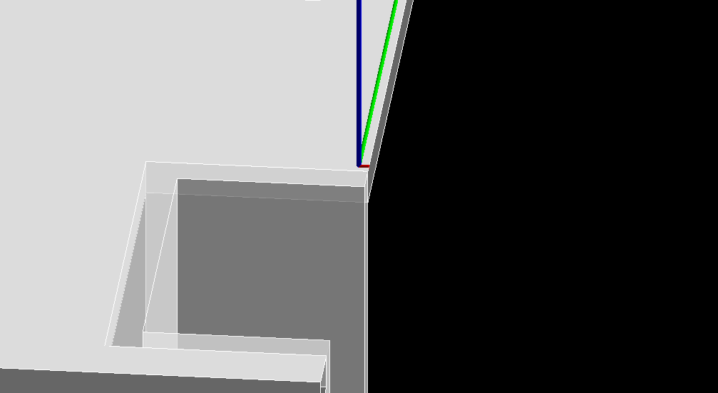
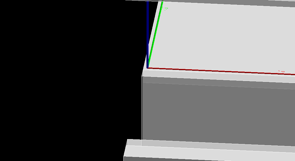
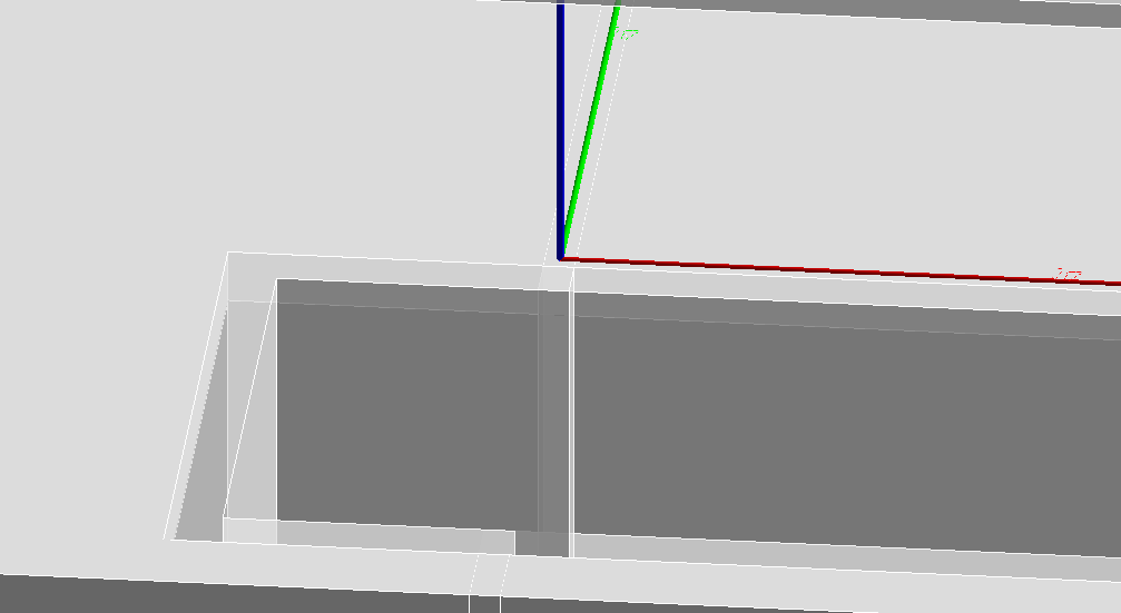
I attached some screenshots depening on whether the two last lines are commented or not. Basically I just want to keep the geometry for -100 < x < 100. Having both lines active does not seem to produce this slice I’m interested in (see cut_both.png).
edit: makes me wonder, is there a way to directly export scoring meshes to for example as hdf5 in that context? i.e., including the geometric info in order to visualize/analyze externally, without having to manually carry the configuration parameters during construction of the mesh?
Thanks for the input! I had a look at ParaView yesterday, looks interesting. I’m using a customized ScoreWriter that writes the complete mesh information (binning, axis ranges, etc.) into a header. I then use a Python script to create a CSV file for ParaView. As you suggested, I can then load the VRML geometry model to be displayed along with the mesh.
Hi John - a quick follow up question:
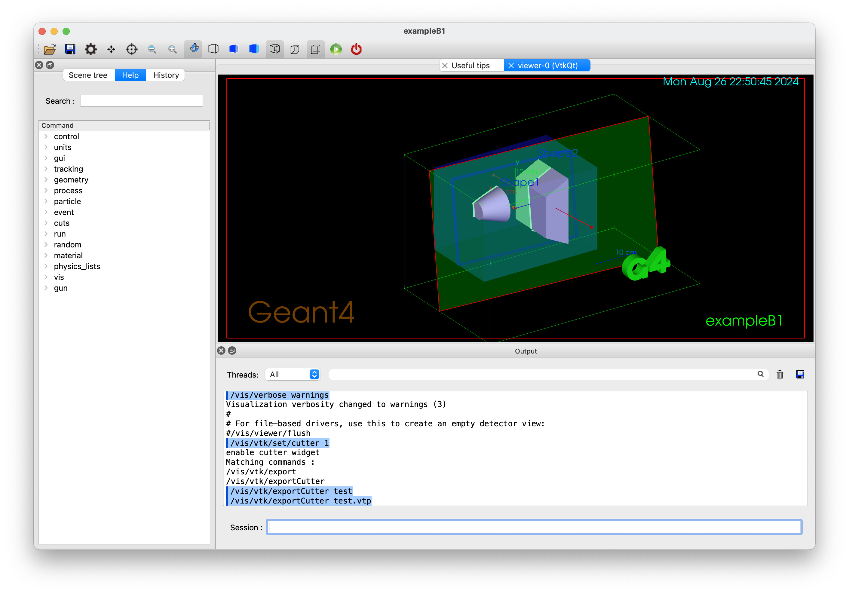
According to the manual, the cutaway feature is available for all drivers yet it does not seem to work with the ToolsSG drivers. Is this work in progress?
What version of Geant4 are you using? We implemented a generic algorithm in 11.1, so it should be available in all drivers. Let us know if it works for you.
I was using 11.01, now just updated to 11.1.1. I forgot to mention that I would like to create a PNG using the TOOLSSG_OFFSCREEN driver. Unfortunately the cutaway features still does not seem to work, I still see the whole geometry:
Sorry, I mixed up the signs when writing the example macro in the post - I’m not using an actual macro but code via UImanager->ApplyCommand(). I’m using the correct normals…
Mmm. You’re right, Dominik. At the moment I’m treating this as a bug in the generic cutaway algorithm, G4VSceneHandler::CreateCutawaySolid…or in G4PhysicalVolumeModel::DescribeSolid. Feel free to help debug it. I’m going to try to contact the original author. I’ll get to it myself hopefully later today.
I should really read the manual more carefully, sectionPlane was basically what I have been looking for. This works also with the TOOLSSG_OFFSCREEN driver, many thanks John!
I would be great though if the cutaway issue could be fixed at some point as it allows a more fine grained control over the “thickness” of the slice (I’m happy to test possible fixes and I will try to have a look myself) Also, in my case the sectionPlane produces a lot of warnings of the sort:
-------- WWWW ------- G4Exception-START -------- WWWW -------
*** G4Exception : GeomMgt0001
      issued by : G4IntersectionSolid::BoundingLimits()
Bad bounding box (min >= max) for solid: sectioned_solid !
pMin = (5136.34,-19.05,-42.5)
pMax = (19.05,19.05,42.5)
*** This is just a warning message. ***
-------- WWWW -------- G4Exception-END --------- WWWW -------

-----------------------------------------------------------
    *** Dump for Boolean solid - sectioned_solid ***
    ===================================================
 Solid type: G4IntersectionSolid
 Parameters of constituent solids:
===========================================================
-----------------------------------------------------------
    *** Dump for solid - th_colli ***
    ===================================================
Solid type: G4Box
Parameters:
   half length X: 19.05 mm
   half length Y: 19.05 mm
   half length Z: 42.5 mm
-----------------------------------------------------------
-----------------------------------------------------------
    *** Dump for Displaced solid - placedB ***
    ===================================================
 Solid type: G4DisplacedSolid
 Parameters of constituent solid:
===========================================================
-----------------------------------------------------------
    *** Dump for solid - _sectioner ***
    ===================================================
Solid type: G4Box
Parameters:
   half length X: 10828.20391385386 mm
   half length Y: 10828.20391385386 mm
   half length Z: 0.1082820391385386 mm
-----------------------------------------------------------
===========================================================
 Transformations:
    Direct transformation - translation :
           (5136.45,-2178.45,3704.9)
                          - rotation    :

   [ ( -6.12323e-17             0            -1)
     (           0            -1             0)
     (          -1             0   6.12323e-17) ]

===========================================================
===========================================================
Hi there
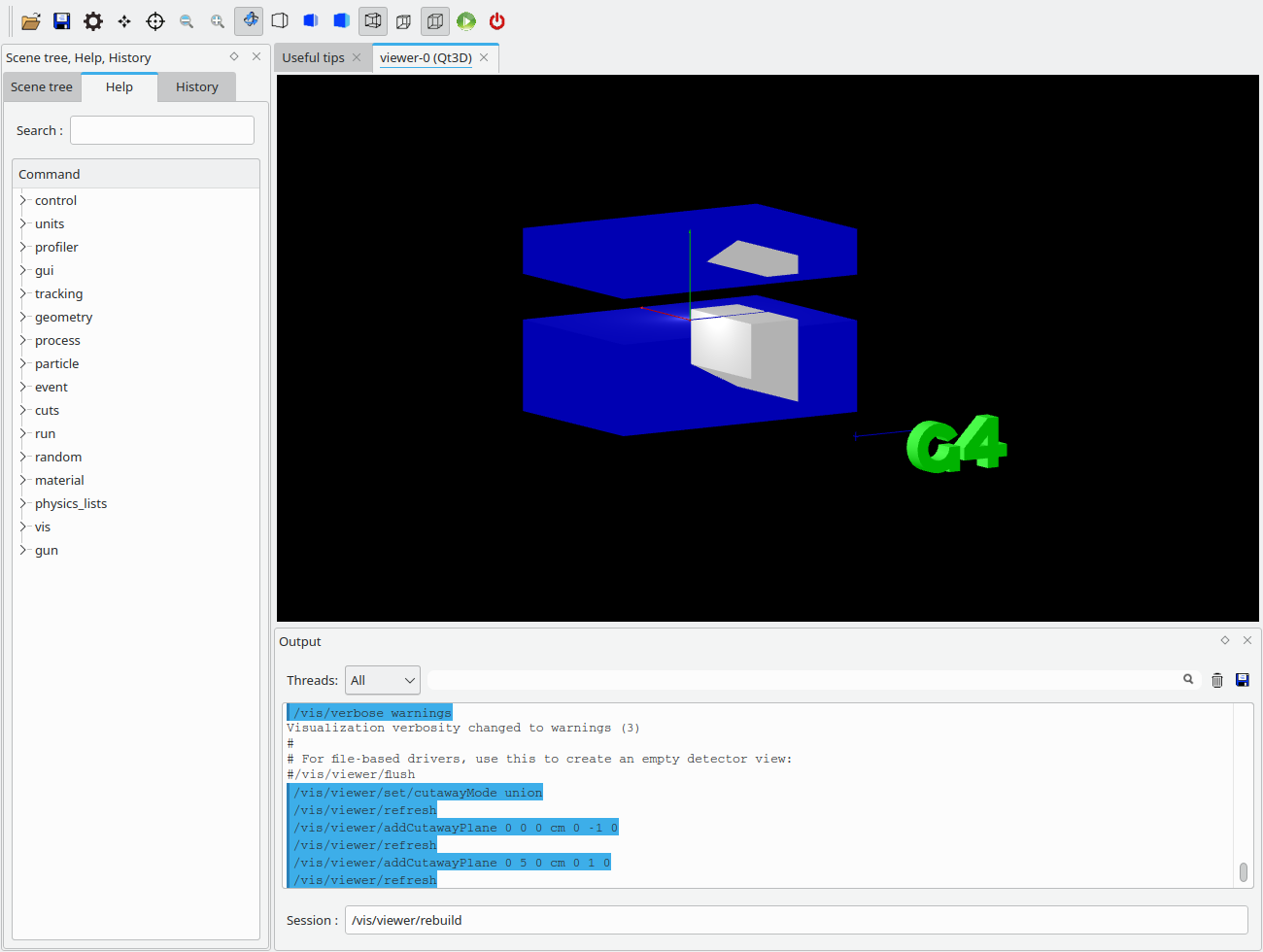
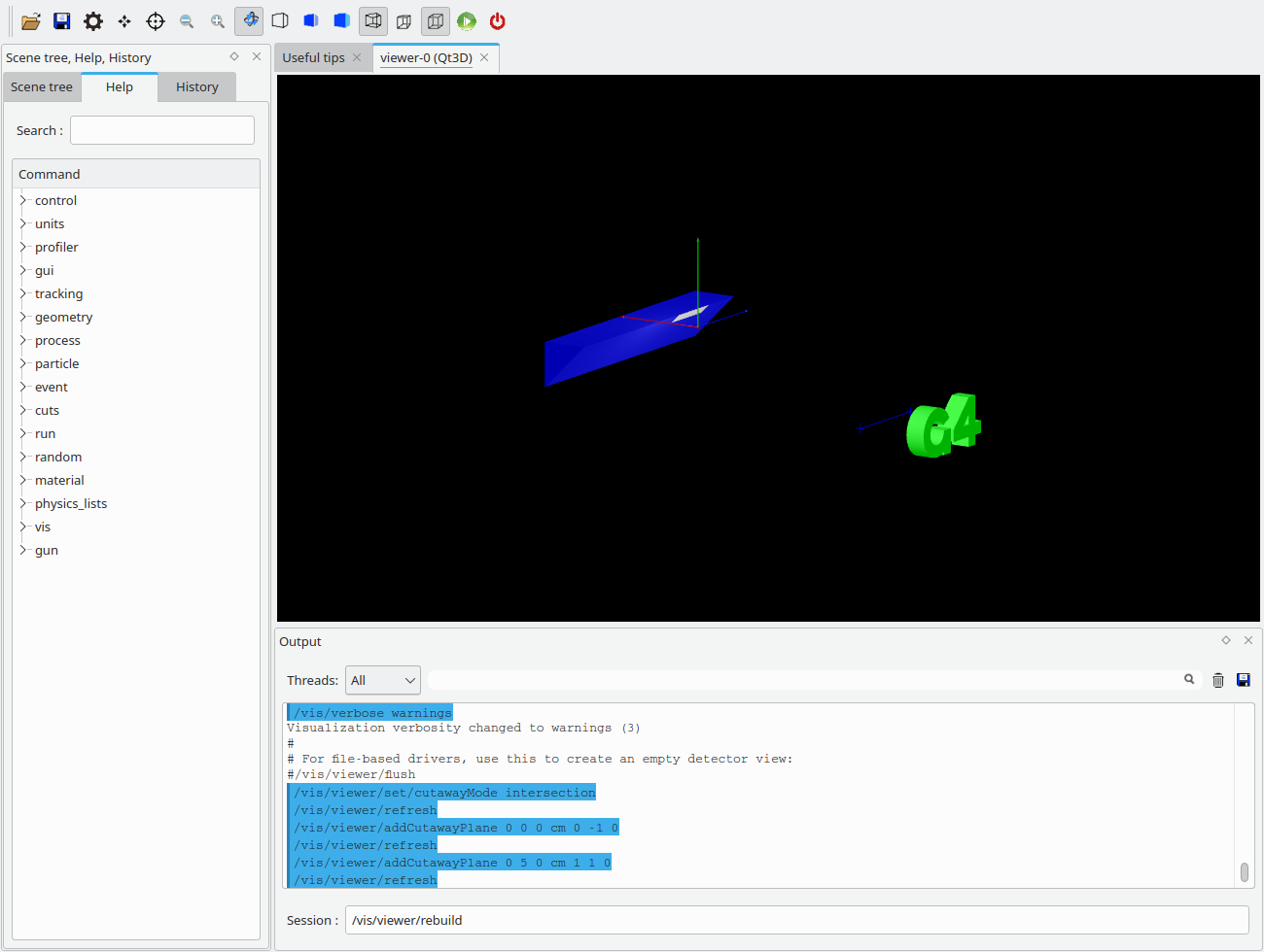
It seems that the generic cutaway does not works for cutting with parallel planes, but hopefully john’s diff works fine. I ran exampleb1 (with Qt3D) with the following macro:
/vis/viewer/set/cutawayMode intersection # union
/vis/viewer/addCutawayPlane 0 0 0 cm 0 1 0
/vis/viewer/addCutawayPlane 0 5 0 cm 0 -1 0
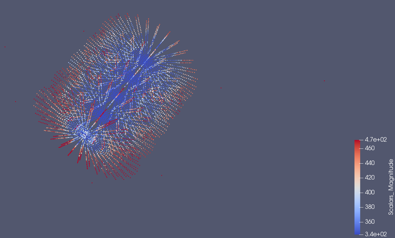
I exported with the vtk vis driver straight into paraview. I dont really have much control over it yet but it seems like an interesting concept. It would be ideal if i figure out how to add tracks too or use paraview more advanced plotting features for instance to integrate fluence at a subset of a location. Though ofcourse you can do that with a new mesh. I am wondering if someone had developed this workflow and has an example?